00197082-03_AI_MTC2_at-Loc2_X-Series-S_DE_EN.pdf - 第62页
3 Installation 3.3 Converting the Cover Guide 62 Assembly Instructions / Montageanleitung SIPLACE X-Series S MTC2 at Location 2 MTC2 an Stellplatz 2 05/2019 3.3 Converting the Cover Guide In addition to the MTC frame, yo…
3 Installation
3.2 Assembling the MTC2 Frame
Assembly Instructions / Montageanleitung SIPLACE X-Series S MTC2 at Location 2 MTC2 an Stellplatz 2 05/2019 61
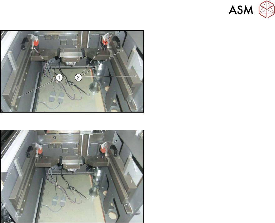
Fig.16: Fastening the slide-in framework
► Slide in the MTC2 slide-in framework at
installation position 3.
► Loosely tighten the screws (1).
► Tighten the screws (2) on the outer
side of the machine.
► Now tighten the screws at (1).
Fig.17: Slide-in framework when fitted
Installed MTC slide-in framework
3 Installation
3.3 Converting the Cover Guide
62 Assembly Instructions / Montageanleitung SIPLACE X-Series S MTC2 at Location 2 MTC2 an Stellplatz 2 05/2019
3.3 Converting the Cover Guide
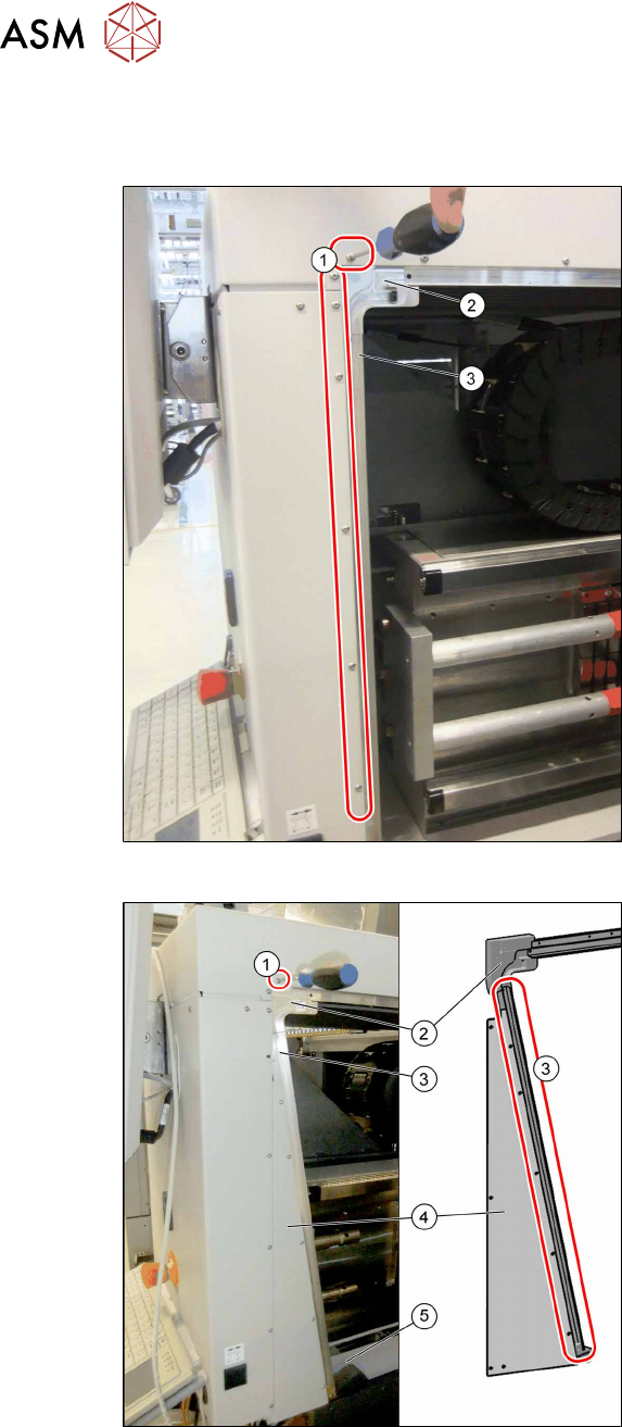
In addition to the MTC frame, you also need to convert the rail on the cover.
Fig.18: Removing the left-hand rail
► Remove the fastening screws(1).
► Remove the corner guide(2) and the
rail(3).
Fig.19: Fitting the new left-hand rail
► Install the following parts:
– The triangular distance sheet (4)
– The new rail (3)
– The guide "left corner SX4as/av
MTC" (2)
– The fastening "Stiffener rail bumper
2/4 SX4av MTC" (5)
► Fix the distance sheet and the rail with
the screws (3) (M3x6), from position (1).
Secure the screws with Loctite 241.
Make sure that any transitions in the rail
are aligned without impact edges.
3 Installation
3.3 Converting the Cover Guide
Assembly Instructions / Montageanleitung SIPLACE X-Series S MTC2 at Location 2 MTC2 an Stellplatz 2 05/2019 63
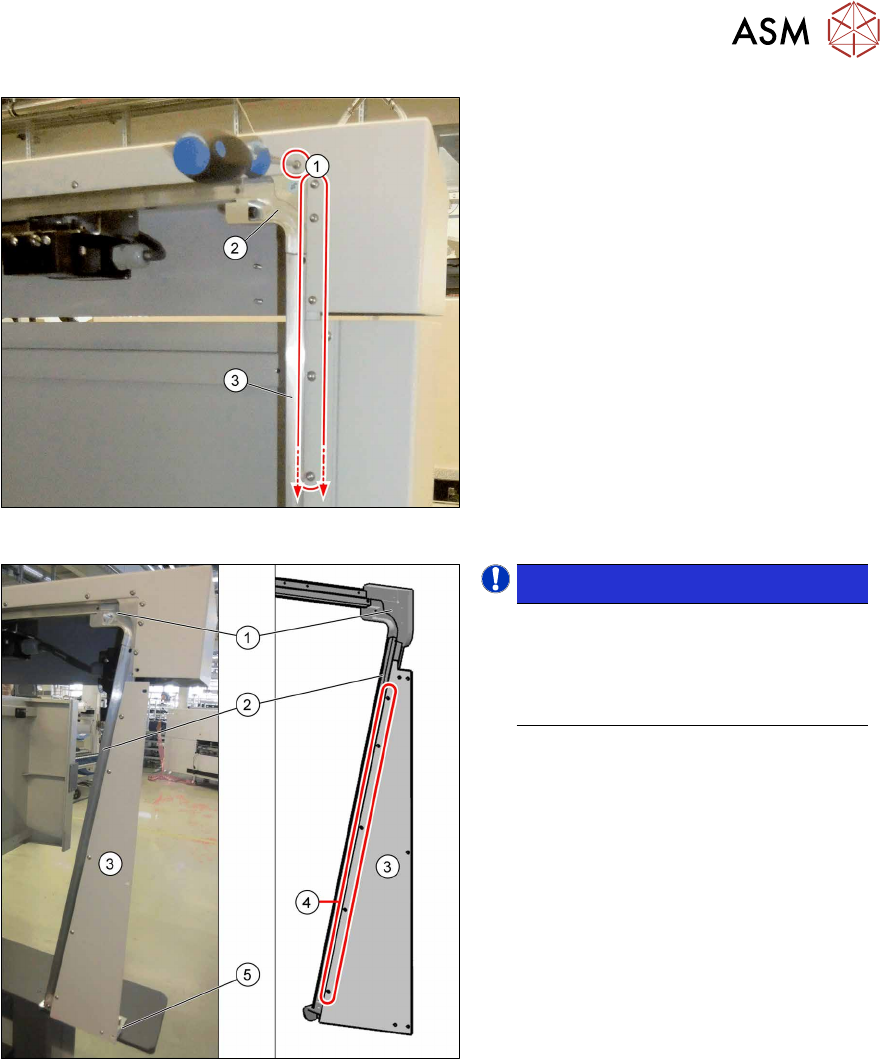
Fig.20: Removing the right-hand rail
► Remove the screws(1) on the outside
of the location.
► Remove the rail (3) and the corner (2).
► Open the service flap and remove the
lower protective plate.
Fig.21: Fitting the new right-hand rail
NOTICE!
Secure all the screws on the rail, the
distance sheet and the corner with
Loctite 241. Make sure that all trans-
itions in the rail are aligned without im-
pact edges.
.
► Insert the new rail (2) and the new
corner (1) and use the screws (M3x6)
to fix these at the top to the machine.
► Fix the slanted distance sheet (3) to the
front of the rail, using the screws
(M3x6) (4).
► Fasten the "bracket assy" to the
machine base with two screws (M5x12)
and the distance sheet with one screw
(M3x6) to the bracket (5).