00197082-03_AI_MTC2_at-Loc2_X-Series-S_DE_EN.pdf - 第65页
3 Installation 3.5 Using the MTC with a SIPLACE CPP Assembly Instructions / Montageanleitung SIPLACE X-Series S MTC2 at Location 2 MTC2 an Stellplatz 2 05/2019 65 3.5 Using the MTC with a SIPLACE CPP CAUTION Crash hazard…
3 Installation
3.4 MTC Connections
64 Assembly Instructions / Montageanleitung SIPLACE X-Series S MTC2 at Location 2 MTC2 an Stellplatz 2 05/2019
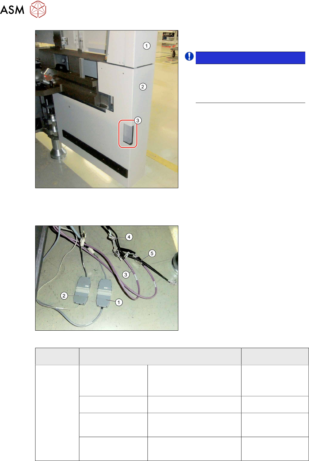
Fig.22: Fitting the protective cover
► Close the service flap (1).
► Fit the protective cover (2).
NOTICE!
Recess
If your machine does not have a
corner cover with a small recess (3),
replace the cover with a new corner
cover.
.
3.4 MTC Connections
Fig.23: Connecting the MTC cables
► Pull the cable out of the inside of the
machine.
► Connect the safety adapter cable for
MTC X1*3 to X1*3 connector MiniMate-
N-LOK X1*3 (12 pin) at X123 (1).
► Connect the X1*2 cable to X1*2 (9-pin)
to X122 (9‑pin)(2).
► Connect the purple cables (3) for the
MTC with the adapter cables (4) to the
connector for the black cable (5).
► Plug the purple cables of the slide-in
framework into the inner connectors of
the adapter cable and the CAN cables
from the machine into the outer ones.
MTC SIPLACE X-Series S
(location 2)
XS_ODU
ODU con-
nector on
slide-in frame-
work
Component signaling
(location addressing)
X1*2 /
00272646003726-W1
X122 03002530-xx
Safety loop X1*3 /
00272646003726-W1
X123 03002531-xx
CAN bus / 1 Wire (in)
X1*5 / W1
Adapter cable CAN bus MTC2
03027905- <== X1*5a / X1*5
==>
X1*5 03027905-xx
CAN bus / 1 wire (out)
X1*6 / W2
Adapter cable CAN bus MTC2
03027905- <== X1*6a / X1*6
==>
X1*6 03027905-xx
3 Installation
3.5 Using the MTC with a SIPLACE CPP
Assembly Instructions / Montageanleitung SIPLACE X-Series S MTC2 at Location 2 MTC2 an Stellplatz 2 05/2019 65
3.5 Using the MTC with a SIPLACE CPP
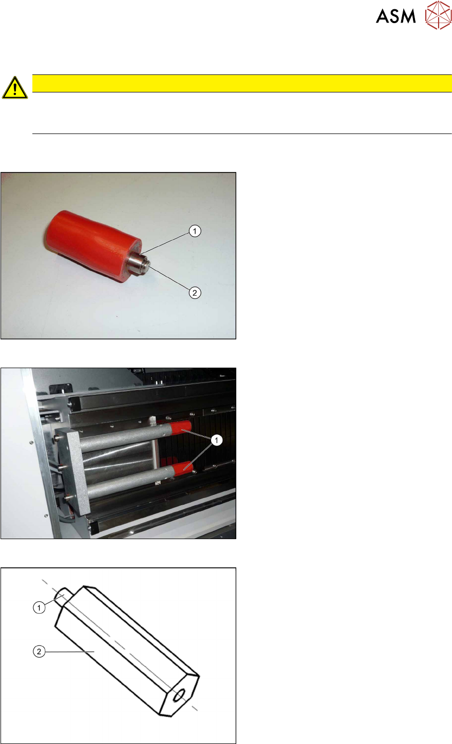
CAUTION
Crash hazard
When using a SIPLACE CPP with the MTC you also need to limit the travel path, otherwise
there is a risk of a crash occurring.
The SIPLACE CPP can generally be installed in machines of types X3 S and X2 S. The SIPLACE
CPP with MTC is available as a special configuration for the machine type X4 S.
Fig.24: Buffer and bushing
► During the following removal, make
sure that the sleeves(1) do not slide
over the screws(2) (M8) and out of the
buffers.
Fig.25: Removing the buffer
► Unscrew the buffer (1) with a size 6
key.
Fig.26: Extension
1. M8 thread
2. 70mm extension (adjustment) stop Y
axis for MTC [03075963‑xx] (2x)
3 Installation
3.6 Final Work:
66 Assembly Instructions / Montageanleitung SIPLACE X-Series S MTC2 at Location 2 MTC2 an Stellplatz 2 05/2019
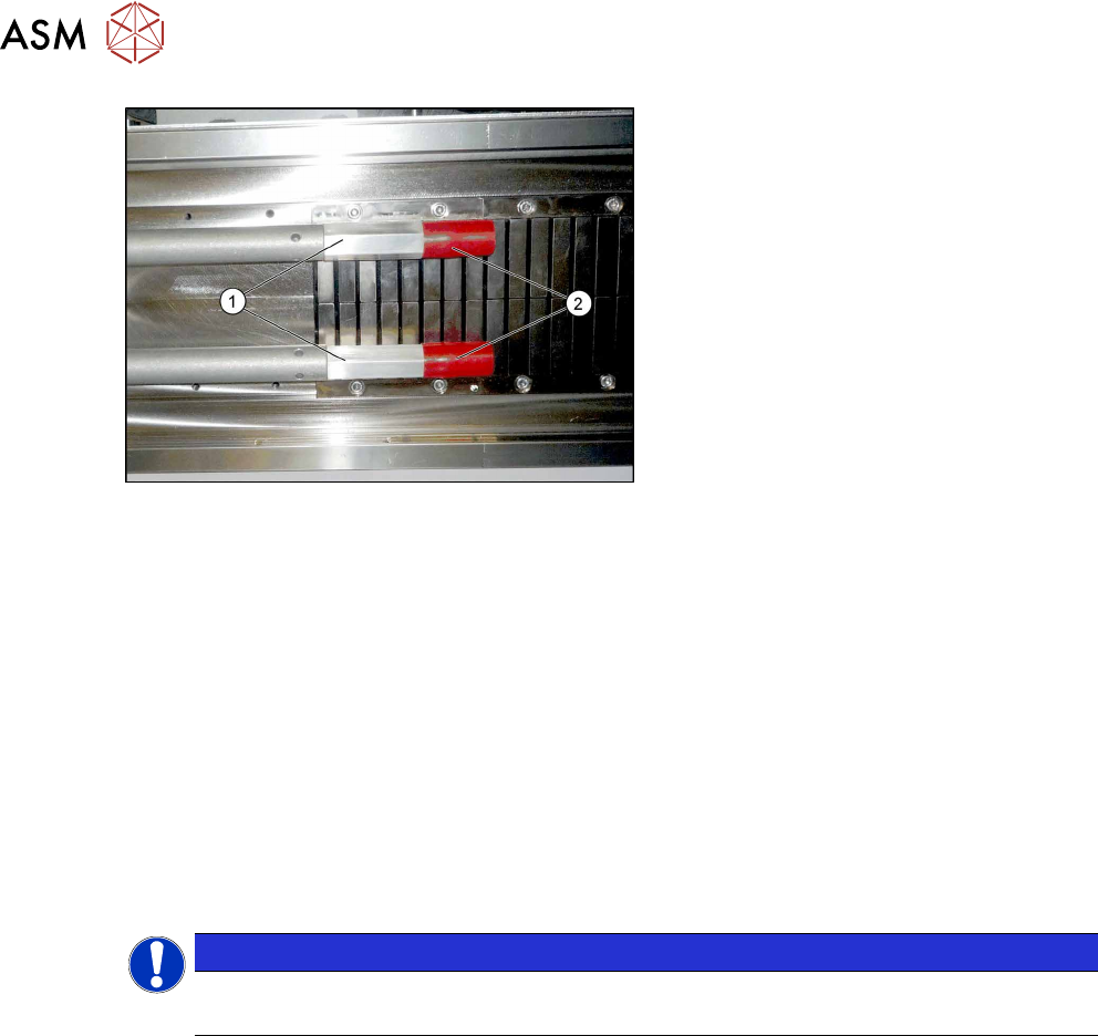
Fig.27: Fitting the buffer
► First fit the two extensions(1).
► Then fit the two buffers(2) (M8) onto
the extensions.
► If you are using an older MTC, you may need to replace the existing version with the "pedestal
with notch" [03010773-xx] from the "retrofit kit for MTC2-CPP head" [03077244-xx] on the
MTC. The pedestal may only have a maximum length of 103 mm, otherwise there is a risk of
crashing with the SIPLACE CPP.
3.6 Final Work:
► Restore the power connection to the MTC2 and the machine.
► Switch the machine on at the main switch.
► Move the component trolley and the MTC2 into the machine.
► Configure the "new" components in the SIPLACE Pro Station Editor and in the station soft-
ware "machine configuration".
► Perform a reference run.
NOTICE
Travel range
The travel range for gantry 2 needs to be reconfigured.
► Start the machine software, log in as Service and then, after the reference run, switch over to
the machine calibration menu (open-ended spanner).
► Start the calibration for gantry 2 travel range and machine zero point.
► Go to -> Calibrate -> Feeder modules -> Calibrate location 2
► Measure the fiducials on the MTC2.
► Copy the MTC2 data to the machine database for the placement station and back this up, if
required, on a data carrier.