00197082-03_AI_MTC2_at-Loc2_X-Series-S_DE_EN.pdf - 第66页
3 Installation 3.6 Final Work: 66 Assembly Instructions / Montageanleitung SIPLACE X-Series S MTC2 at Location 2 MTC2 an Stellplatz 2 05/2019 Fig.27: Fitting the buffer ► First fit the two extensions (1) . ► Then fit t…
3 Installation
3.5 Using the MTC with a SIPLACE CPP
Assembly Instructions / Montageanleitung SIPLACE X-Series S MTC2 at Location 2 MTC2 an Stellplatz 2 05/2019 65
3.5 Using the MTC with a SIPLACE CPP
CAUTION
Crash hazard
When using a SIPLACE CPP with the MTC you also need to limit the travel path, otherwise
there is a risk of a crash occurring.
The SIPLACE CPP can generally be installed in machines of types X3 S and X2 S. The SIPLACE
CPP with MTC is available as a special configuration for the machine type X4 S.
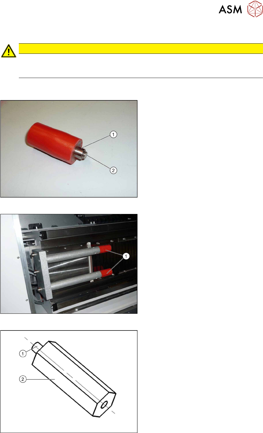
Fig.24: Buffer and bushing
► During the following removal, make
sure that the sleeves(1) do not slide
over the screws(2) (M8) and out of the
buffers.
Fig.25: Removing the buffer
► Unscrew the buffer (1) with a size 6
key.
Fig.26: Extension
1. M8 thread
2. 70mm extension (adjustment) stop Y
axis for MTC [03075963‑xx] (2x)
3 Installation
3.6 Final Work:
66 Assembly Instructions / Montageanleitung SIPLACE X-Series S MTC2 at Location 2 MTC2 an Stellplatz 2 05/2019
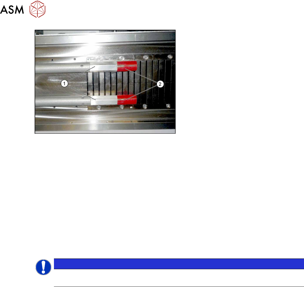
Fig.27: Fitting the buffer
► First fit the two extensions(1).
► Then fit the two buffers(2) (M8) onto
the extensions.
► If you are using an older MTC, you may need to replace the existing version with the "pedestal
with notch" [03010773-xx] from the "retrofit kit for MTC2-CPP head" [03077244-xx] on the
MTC. The pedestal may only have a maximum length of 103 mm, otherwise there is a risk of
crashing with the SIPLACE CPP.
3.6 Final Work:
► Restore the power connection to the MTC2 and the machine.
► Switch the machine on at the main switch.
► Move the component trolley and the MTC2 into the machine.
► Configure the "new" components in the SIPLACE Pro Station Editor and in the station soft-
ware "machine configuration".
► Perform a reference run.
NOTICE
Travel range
The travel range for gantry 2 needs to be reconfigured.
► Start the machine software, log in as Service and then, after the reference run, switch over to
the machine calibration menu (open-ended spanner).
► Start the calibration for gantry 2 travel range and machine zero point.
► Go to -> Calibrate -> Feeder modules -> Calibrate location 2
► Measure the fiducials on the MTC2.
► Copy the MTC2 data to the machine database for the placement station and back this up, if
required, on a data carrier.
4 Appendix
4.1 Excerpts from the Service Manual
Assembly Instructions / Montageanleitung SIPLACE X-Series S MTC2 at Location 2 MTC2 an Stellplatz 2 05/2019 67
4 Appendix
4.1 Excerpts from the Service Manual
The following chapters are excerpts from the service manual for your machine. If required, further
information is provided there.
●
Service manual "SIPLACE X-Series S" [DE:00197041-xx] [EN:00197042‑xx]
4.1.1 Dismantling the Lower Side Cover
Most tasks require that you dismantle the lower side cover from the location. This is shown below
using the example of location 2. The procedure for other locations is identical.
Parts, equipment and tools
●
Shortened Allen key, if required
Dismantling the side cover
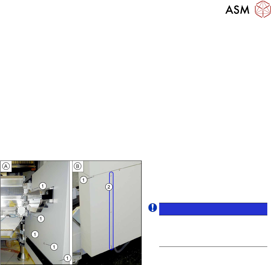
Fig.28: Dismantling the lower side cover
► While unscrewing, always hold on to
the side cover, to prevent it falling off.
► Remove the six screws(1) fastening
the inner(A) and outer side(B) of the
side panel.
NOTICE!
The three fastening screws (2) on the
outer side are loosened as a default.
The side cover can be pulled out here.
.
► Remove the side cover.
Fitting the side cover
► Assembly is performed by following the above instructions in the reverse order.