00197082-03_AI_MTC2_at-Loc2_X-Series-S_DE_EN.pdf - 第63页
3 Installation 3.3 Converting the Cover Guide Assembly Instructions / Montageanleitung SIPLACE X-Series S MTC2 at Location 2 MTC2 an Stellplatz 2 05/2019 63 Fig.20: Removing the right-hand rail ► Remove the screws (1) …
3 Installation
3.3 Converting the Cover Guide
62 Assembly Instructions / Montageanleitung SIPLACE X-Series S MTC2 at Location 2 MTC2 an Stellplatz 2 05/2019
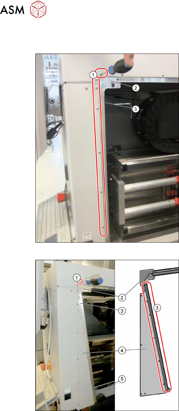
3.3 Converting the Cover Guide
In addition to the MTC frame, you also need to convert the rail on the cover.
Fig.18: Removing the left-hand rail
► Remove the fastening screws(1).
► Remove the corner guide(2) and the
rail(3).
Fig.19: Fitting the new left-hand rail
► Install the following parts:
– The triangular distance sheet (4)
– The new rail (3)
– The guide "left corner SX4as/av
MTC" (2)
– The fastening "Stiffener rail bumper
2/4 SX4av MTC" (5)
► Fix the distance sheet and the rail with
the screws (3) (M3x6), from position (1).
Secure the screws with Loctite 241.
Make sure that any transitions in the rail
are aligned without impact edges.
3 Installation
3.3 Converting the Cover Guide
Assembly Instructions / Montageanleitung SIPLACE X-Series S MTC2 at Location 2 MTC2 an Stellplatz 2 05/2019 63
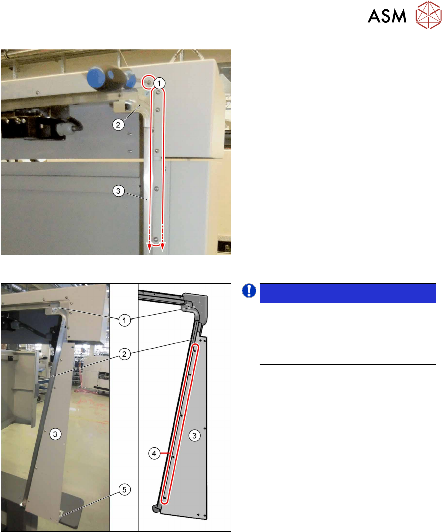
Fig.20: Removing the right-hand rail
► Remove the screws(1) on the outside
of the location.
► Remove the rail (3) and the corner (2).
► Open the service flap and remove the
lower protective plate.
Fig.21: Fitting the new right-hand rail
NOTICE!
Secure all the screws on the rail, the
distance sheet and the corner with
Loctite 241. Make sure that all trans-
itions in the rail are aligned without im-
pact edges.
.
► Insert the new rail (2) and the new
corner (1) and use the screws (M3x6)
to fix these at the top to the machine.
► Fix the slanted distance sheet (3) to the
front of the rail, using the screws
(M3x6) (4).
► Fasten the "bracket assy" to the
machine base with two screws (M5x12)
and the distance sheet with one screw
(M3x6) to the bracket (5).
3 Installation
3.4 MTC Connections
64 Assembly Instructions / Montageanleitung SIPLACE X-Series S MTC2 at Location 2 MTC2 an Stellplatz 2 05/2019
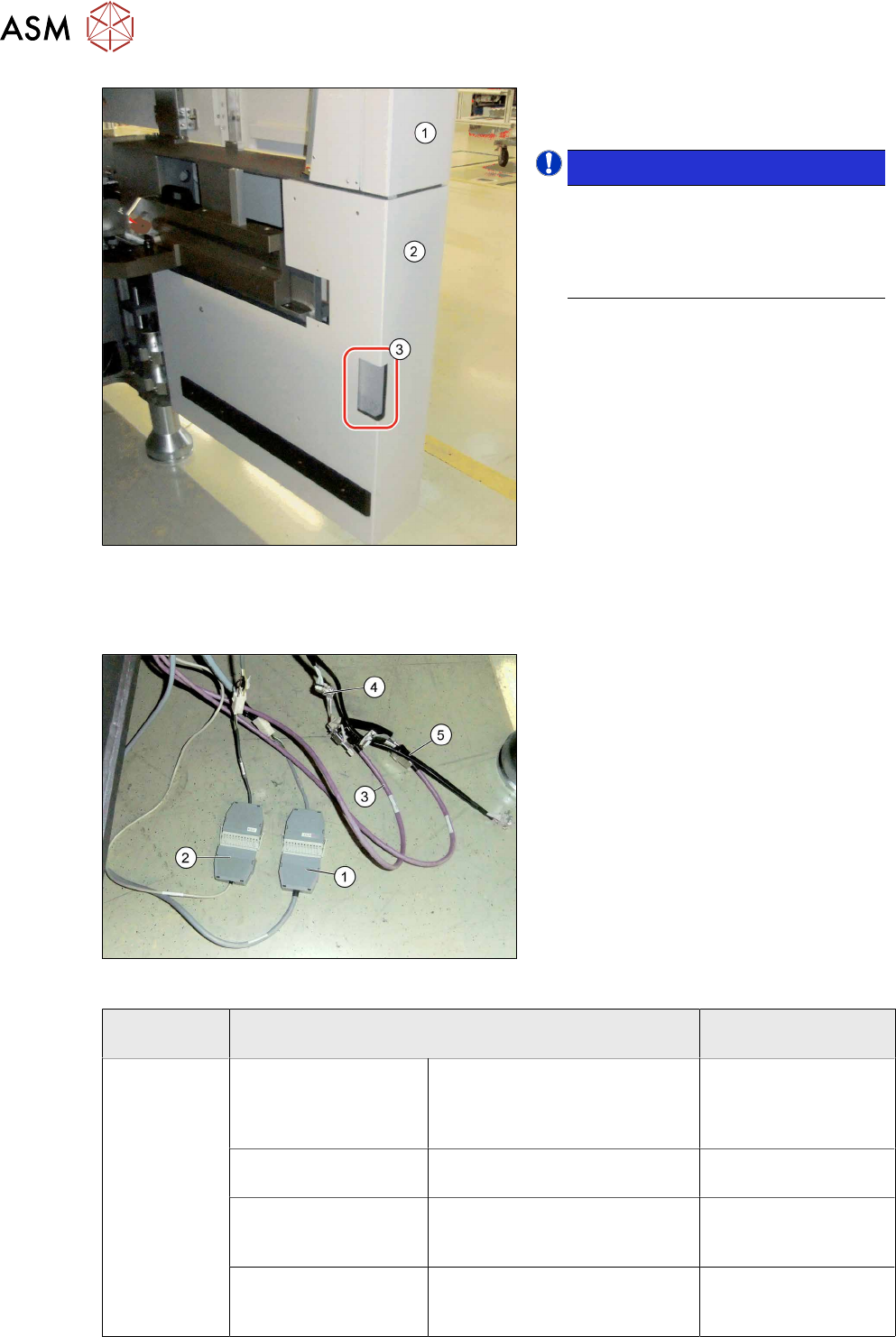
Fig.22: Fitting the protective cover
► Close the service flap (1).
► Fit the protective cover (2).
NOTICE!
Recess
If your machine does not have a
corner cover with a small recess (3),
replace the cover with a new corner
cover.
.
3.4 MTC Connections
Fig.23: Connecting the MTC cables
► Pull the cable out of the inside of the
machine.
► Connect the safety adapter cable for
MTC X1*3 to X1*3 connector MiniMate-
N-LOK X1*3 (12 pin) at X123 (1).
► Connect the X1*2 cable to X1*2 (9-pin)
to X122 (9‑pin)(2).
► Connect the purple cables (3) for the
MTC with the adapter cables (4) to the
connector for the black cable (5).
► Plug the purple cables of the slide-in
framework into the inner connectors of
the adapter cable and the CAN cables
from the machine into the outer ones.
MTC SIPLACE X-Series S
(location 2)
XS_ODU
ODU con-
nector on
slide-in frame-
work
Component signaling
(location addressing)
X1*2 /
00272646003726-W1
X122 03002530-xx
Safety loop X1*3 /
00272646003726-W1
X123 03002531-xx
CAN bus / 1 Wire (in)
X1*5 / W1
Adapter cable CAN bus MTC2
03027905- <== X1*5a / X1*5
==>
X1*5 03027905-xx
CAN bus / 1 wire (out)
X1*6 / W2
Adapter cable CAN bus MTC2
03027905- <== X1*6a / X1*6
==>
X1*6 03027905-xx