00197082-03_AI_MTC2_at-Loc2_X-Series-S_DE_EN.pdf - 第69页
4 Appendix 4.2 Circuit Diagrams Assembly Instructions / Montageanleitung SIPLACE X-Series S MTC2 at Location 2 MTC2 an Stellplatz 2 05/2019 69 1 1 3 2 Fig.29: Mounting tool 1. Fixtures 2. Mounting tool 3. Eyelet ► Attac…

4 Appendix
4.1 Excerpts from the Service Manual
68 Assembly Instructions / Montageanleitung SIPLACE X-Series S MTC2 at Location 2 MTC2 an Stellplatz 2 05/2019
4.1.2 Replacing the COT Insert Assembly
NOTICE
Working on the COT-i without complete removal of this
For some tasks on the COT-i, it may be enough to just pull the COT-i slightly out of the
machine. In this case, follow the procedure for replacement but observe the following
instructions:
► Remove the screws fastening the central unit and the lifting mechanics.
► You usually do not need to disconnect the cable. However, if the cable is too short,
unplug it.
► Slightly pull the COT-i out of the machine.
Parts, equipment and tools
●
SIPLACE X3 S, X4 S: COT insert X4 S [03098442-xx]
or
SIPLACE X4i S: COT insert X4i S [03093204-xx]
●
Circuit diagram X-Series S [00197021-xx] (German/English)
●
Mounting tool [03015976-xx]
●
Suitable lifting device (e.g. hand-operated crane)
CAUTION
Heavy machine part!
The COT insert is heavy. To lift it out, you will need to use the mounting tool and a suitable
lifting device (hand-operated crane etc.).
Removal
► Switch off the machine, disconnect it from the power supply and secure it to prevent
unauthorized reactivation.
1.2 "Preparatory work..." [}46]
► Switch off the compressed air supply
► Dismantle the nozzle changer.
► Disconnect the COT insert from all electrical and pneumatic connections. Mark the positions
of these connections, to make clear assignment easier later on. The connection cables and
hoses are located behind the COT insert – in the space leading to the machine base (under
the nozzle changer).
► Dismantle the lower side covers on both sides of the location, so that you can lift the COT in-
sert out later on.
4.1.1 "Dismantling the Lower Side Cover" [}67]
4 Appendix
4.2 Circuit Diagrams
Assembly Instructions / Montageanleitung SIPLACE X-Series S MTC2 at Location 2 MTC2 an Stellplatz 2 05/2019 69
1
1
3
2
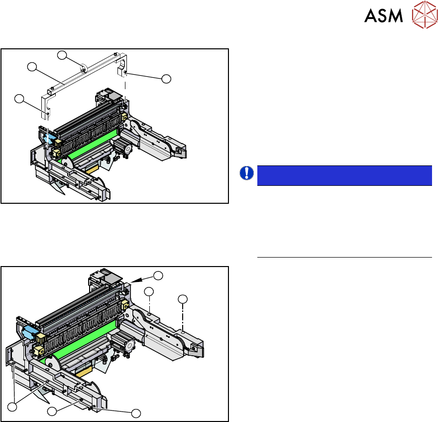
Fig.29: Mounting tool
1. Fixtures
2. Mounting tool
3. Eyelet
► Attach the mounting tool (2) to the fix-
tures provided (1) on the COT insert.
► Fix the lifting device to the eyelet (3) of
the mounting tool (2).
NOTICE!
The COT insert can be installed at dif-
ferent positions in the machine loca-
tion. Mark the position of your COT in-
sert, to ensure that this is sub-
sequently returned to its original posi-
tion.
.
1
1
1
1
2
1
Fig.30: Fastening screws
► Remove the eight fastening screws(1)
of the COT insert.
► Lift the complete COT insert out of the
machine and place it on a suitable sur-
face (four wooden blocks etc.).
► Make sure that you do not damage any
valves, connection cables, hoses etc.
Installation
► Attach the mounting tool to the new COT insert and lift it into the machine, with the help of the
lifting device.
► Reconnect all cables. If required, use the detailed circuit diagrams to help you.
► Move the COT insert into its final position (to the previously marked installation position).
Take care not to damage the cables and hoses.
► Further installation is performed by following the above instructions in the reverse order.
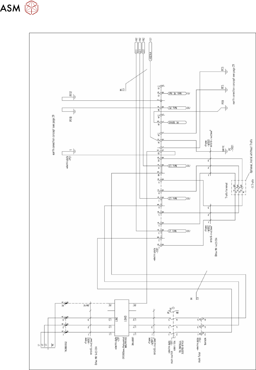
4.2 Circuit Diagrams
For more information, refer to the circuit diagrams folder:
●
Detailed circuit diagrams folder for SIPLACE X-Series S (up to Gxxxx) [DE+EN:00197021‑xx]
●
Detailed circuit diagrams folder for SIPLACE X-Series S (from Hxxxx) [DE+EN:00197920‑xx]
4 Appendix
4.2 Circuit Diagrams
70 Assembly Instructions / Montageanleitung SIPLACE X-Series S MTC2 at Location 2 MTC2 an Stellplatz 2 05/2019
4.2.1 Circuit Diagram MTC2
Fig.31: Circuit diagram MTC