00197082-03_AI_MTC2_at-Loc2_X-Series-S_DE_EN.pdf - 第70页
4 Appendix 4.2 Circuit Diagrams 70 Assembly Instructions / Montageanleitung SIPLACE X-Series S MTC2 at Location 2 MTC2 an Stellplatz 2 05/2019 4.2.1 Circuit Diagram MTC2 Fig.31: Circuit diagram MTC
4 Appendix
4.2 Circuit Diagrams
Assembly Instructions / Montageanleitung SIPLACE X-Series S MTC2 at Location 2 MTC2 an Stellplatz 2 05/2019 69
1
1
3
2
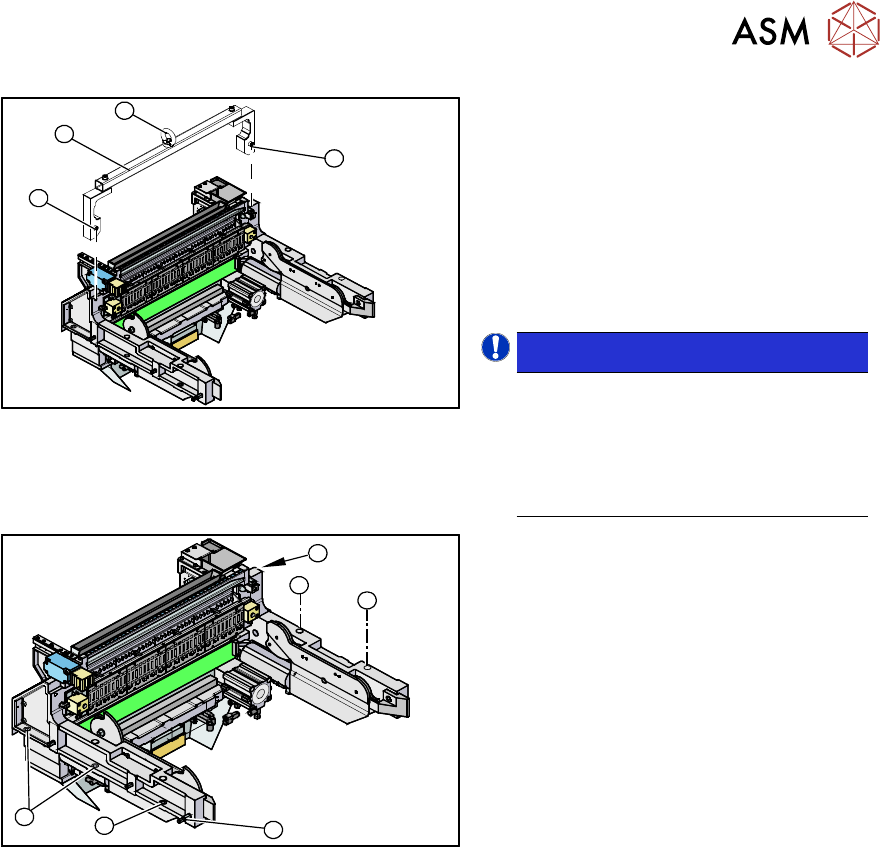
Fig.29: Mounting tool
1. Fixtures
2. Mounting tool
3. Eyelet
► Attach the mounting tool (2) to the fix-
tures provided (1) on the COT insert.
► Fix the lifting device to the eyelet (3) of
the mounting tool (2).
NOTICE!
The COT insert can be installed at dif-
ferent positions in the machine loca-
tion. Mark the position of your COT in-
sert, to ensure that this is sub-
sequently returned to its original posi-
tion.
.
1
1
1
1
2
1
Fig.30: Fastening screws
► Remove the eight fastening screws(1)
of the COT insert.
► Lift the complete COT insert out of the
machine and place it on a suitable sur-
face (four wooden blocks etc.).
► Make sure that you do not damage any
valves, connection cables, hoses etc.
Installation
► Attach the mounting tool to the new COT insert and lift it into the machine, with the help of the
lifting device.
► Reconnect all cables. If required, use the detailed circuit diagrams to help you.
► Move the COT insert into its final position (to the previously marked installation position).
Take care not to damage the cables and hoses.
► Further installation is performed by following the above instructions in the reverse order.
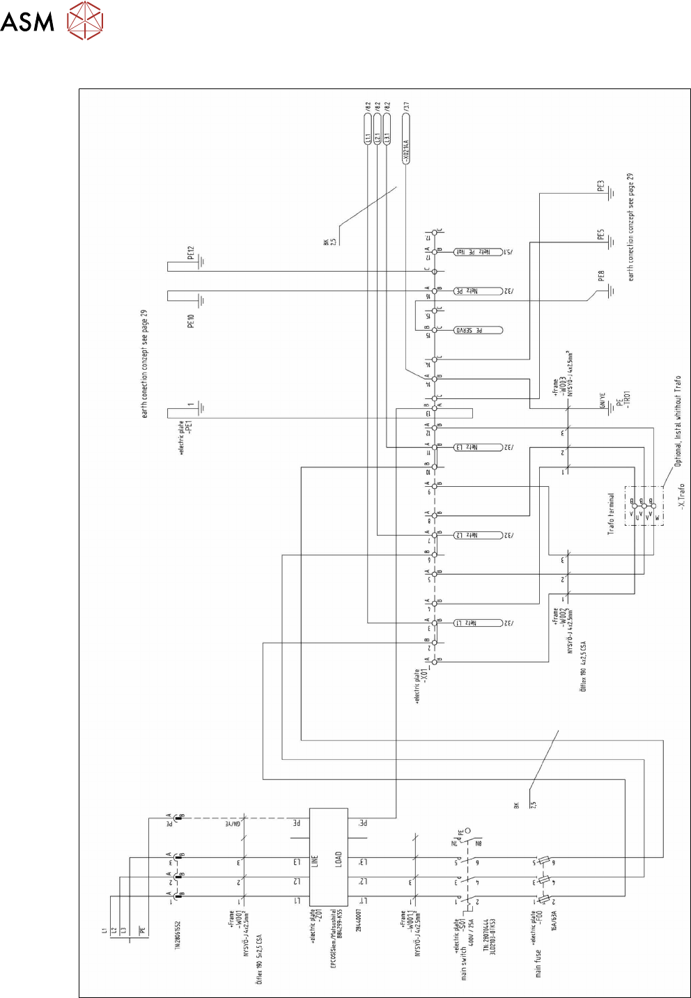
4.2 Circuit Diagrams
For more information, refer to the circuit diagrams folder:
●
Detailed circuit diagrams folder for SIPLACE X-Series S (up to Gxxxx) [DE+EN:00197021‑xx]
●
Detailed circuit diagrams folder for SIPLACE X-Series S (from Hxxxx) [DE+EN:00197920‑xx]
4 Appendix
4.2 Circuit Diagrams
70 Assembly Instructions / Montageanleitung SIPLACE X-Series S MTC2 at Location 2 MTC2 an Stellplatz 2 05/2019
4.2.1 Circuit Diagram MTC2
Fig.31: Circuit diagram MTC