FLX500-maintenance.pdf - 第13页
—9— W ARNING High voltage.— Do not remove any panels or covers on the FLX500 . There ar e no customer-ser- viceable parts behind the covers. High voltage may be present and expose…

Data I/O
FLX500 Chptr 1
—8—
blank page
—9—
WARNING
High voltage.— Do not remove any panels or
covers on the
FLX500
. There are no customer-ser-
viceable parts behind the covers. High voltage
may be present and exposed if covers are
removed. High voltage can cause injury or death.
2 … Periodic
Maintenance

Data I/O
FLX500 Chptr 2
—10—
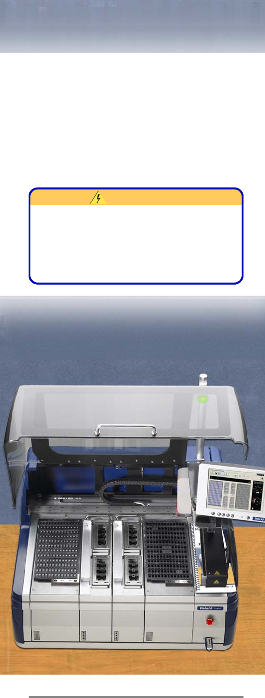
NOTE: Once a year,
FLX500
Programmer
Module performance can be verified or
returned to Data I/O for verification. See
Annual Performance Verification on page
23.
Gantry Movement and
Alignment
The FLX500 gantry scans fiducials on the Tray
Modules and Programmer Modules using an
optical sensor on the PNP Head. This occurs
when programming is started after any module
receives power for the first time.
If you experience any alignment problems, such
as pick and place failures, you can:
• rescan the fiducials at the Diagnostics –Mod-
ules Window
• verify system calibrations at the Diagnostics
–Alignment Window. If the verification fails,
see Calibration Fails in the on-screen Help.
For more information, see the on-screen Help in
the diagnostics area of the application.
Daily Maintenance
Clean the Sockets
Tools Required:
• Shop air, clean and dry, .48-.55 MPa
(70-80 PSI).
• 4 mm Hex Key (Allen Wrench)
Remove dust and debris from the sockets with
clean, dry, compressed air. Actuate the sockets to
ensure dust and debris are cleared from beneath
the contacts. If the Socket Adapter is installed in
the FLX500 programmer, the sockets can be actu-