FLX500-maintenance.pdf - 第22页
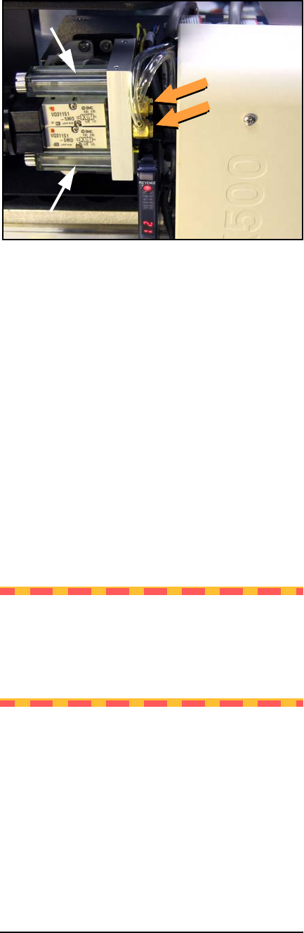
Data I/O FLX500 Chptr 2 —18— Figure 9—Air tubes on barbed fittings—one for each probe—and air filters. 6. Use clean and dry compressed air .48-.62 MPa (70-90 PSI max) to blow into one tube. Stop and start the compr…
2 … Periodic Maintenance Monthly or Quarterly
—17—
Perform the following probe blowout procedure
quarterly and at times when pick failures occur
often. This interval is dependent on the amount
of machine use and air quality. Adjust your inter-
val as required. For example, preventing the
probes from drawing in air for long periods of
non-use—using Automatic Air Management
(see the on-screen Diagnostic Help) or manually
shutting air off to the probes while idle—can
reduce the need to perform this blowout proce-
dure as often.
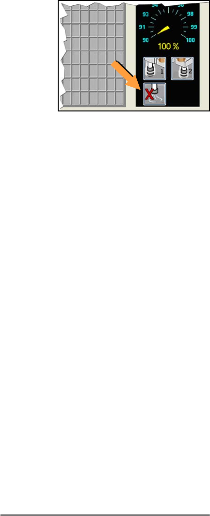
Figure 8—Probe air-shut-off buttons on the Run
Window.
Probe Blowout Procedure
Tools Required:
• Standard (flat) screwdriver
• tape or method to mark tubes
• compressed air, clean and dry, .48-.62
MPa (70-90 PSI)
1. Stop the job if applicable. For instructions
see the on-screen Help.
2. Switch power off.
3. Push the E-Stop
Blow Out the Probes
4. Open the cover and move the PNP Head
close for access to its far side.
5. Locate the two clear tubes just to the far side
of the head cover, plugged into barbed fit-
tings. With a small flat screwdriver pry each
tube off its fitting, marking which tube goes
to which fitting.
Data I/O
FLX500 Chptr 2
—18—
Figure 9—Air tubes on barbed fittings—one for each
probe—and air filters.
6. Use clean and dry compressed air .48-.62
MPa (70-90 PSI max) to blow into one tube.
Stop and start the compressed air flow sev-
eral times.
7. Do the same with the other tube.
Blow Out the Manifold
8. Now locate the two clear, square plastic
housings that hold the filters. Unscrew the
screws securing the housings.
9. Remove the housings, being careful not to
lose their gaskets.
10. Carefully remove the gaskets.
CAUTION: Health Hazard. For the next
step, wear eye protection. The tube fittings
on the manifold are pointed up. When blow-
ing air through the manifold, protect your
eyes and face.
11. Use clean and dry compressed air .48-.62
MPa (70-90 PSI max) to blow into the two
manifold ports now exposed at each filter
site. Stop and start the compressed air flow
several times.
2 … Periodic Maintenance Monthly or Quarterly
—19—
Replace Parts in Reverse Order
NOTE: If filters are dirty (not white by sev-
eral shades and possibly have visible debris)
replace the filters with new ones: see Step 6.–
of Checking Air Filters on page 20.
12. Carefully reinstall the filter gaskets and
housings, and reinstall each screw.
13. Reconnect both tubes onto the correct fit-
tings.
14. Connect shop air at the back of the FLX if it
isn’t already.
Check Vacuum
15. Switch the power on and check the pressure
at each probe tip. You can accomplish this as
follows:
15a.Clean the probe tips.
15b.Ensure that there is a standard output
module installed (not a Drop Module)
without a tray on it.
15c.Release the E-Stop and close the cover.
15d.Open the Diagnostic Window by tap-
ping the Tools button and entering your
PIN.
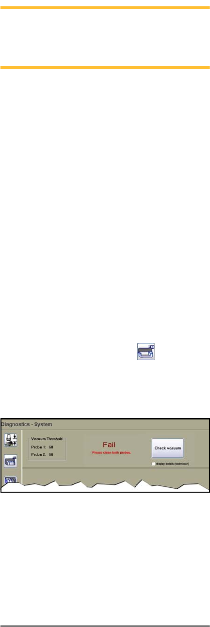
15e.Tap the System button , and then
Check Vacuum.
If any test fails, see Insufficient Vacuum
on page 30.
Figure 10—The Check Vacuum button on the System
Window in the Diagnostics Tools and the Fail mes-
sage when the system does not meet requirements.