FLX500-maintenance.pdf - 第37页
—33— If you wish to contact Data I/O T echnical Sup- port or a service center , see the following pages for information w e need from you as w ell as how to contact us. 4 … Corres…
Data I/O
FLX500 Chptr 3
—32—
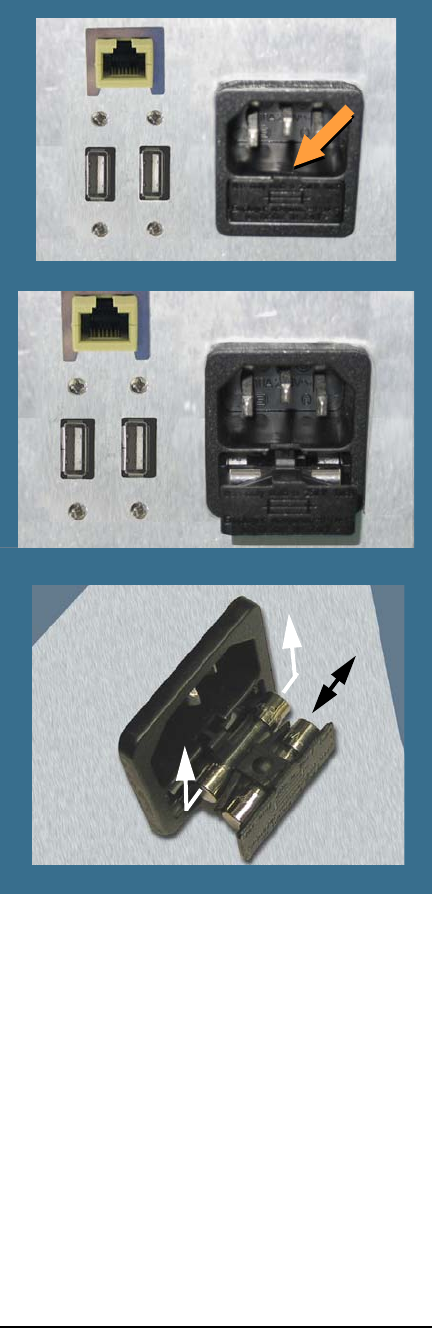
Figure 17—Fuse Access is in the Back. Closed (top)
and open. The nearest fuse is a spare. The spare fuse
slides out left/right unlike the main fuse.
5. To remove the active fuse (farthest in), press
down lightly on the drawer while pushing
up on the fuse.
6. If the fuse is burnt, replace it with the spare,
which slides out left or right.
7. Close the drawer.
8. Plug the power cord back into the FLX.
—33—
If you wish to contact Data I/O Technical Sup-
port or a service center, see the following pages
for information we need from you as well as how
to contact us.
4 … Correspondence
Data I/O
FLX500 Chptr 4
—34—
Information We Need
Please remember to include the following:
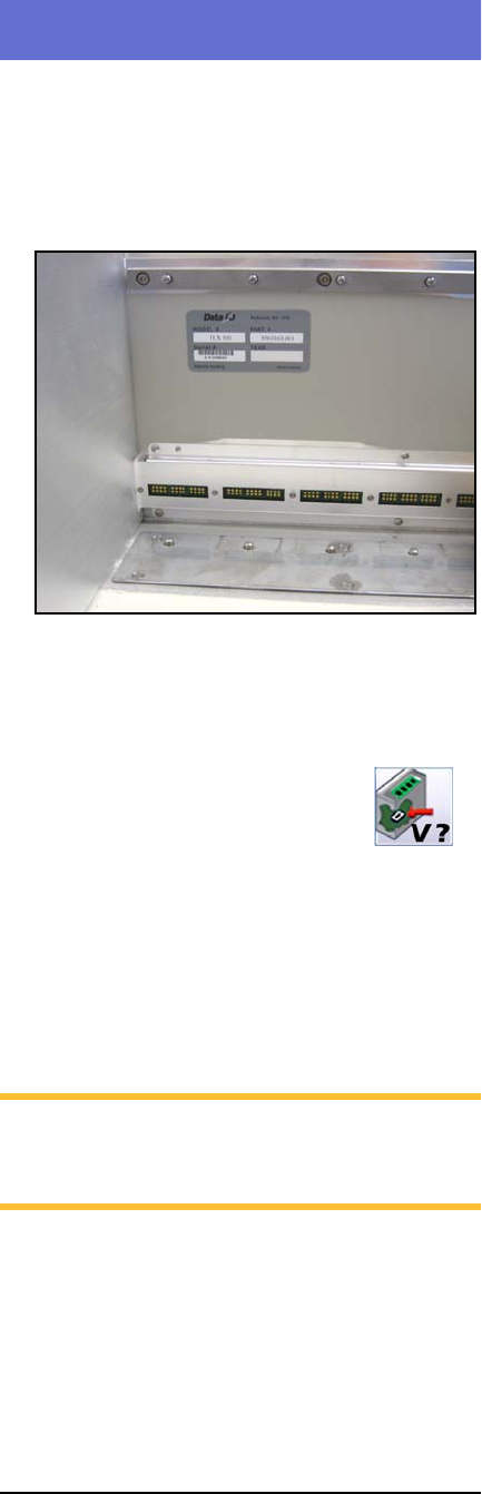
•The FLX Serial Number. It is printed on the
communication wall that is visible when the
modules are removed.
Figure 18—The Serial Number Label is visible after
removing the modules.
•The FLX software and firmware version num-
bers. These are displayed by tapping the Ver-
sion button on the Run Window.
• The log file. See Log File on page 3.
• Results from running the PV-Kit job. See
Rerunning the PV-Kit on page 26.
• Error message, if there is one.
• Device manufacturer and part number, if
device-related.
NOTE: For the latest version of this manual,
see
Support > Technical Library > Manuals
on our Web site.