FLX500-maintenance.pdf - 第33页
3 … Troubleshooting Fiducial Scan Errors —29— Figure 16—PNP Head optic sensor digital display showing a reading of 12. The reading on the top surface of the module should be approximately in th e range 1000--2500. If…

Data I/O
FLX500 Chptr 3
—28—
Figure 15—The bottom of a Programmer Module
allows access to the actuating screws when power to
the programmer is unavailable.
3. Slide the Actuator Plate out from the pro-
grammer.
4. Remove the Socket Adapter in the usual
way. For help removing the adapter, see the
on-screen Help.
Fiducial Scan Errors
If the FLX500 fails to program after the PNP Head
scans the modules, there may be a problem with
the scanning.
NOTE: For accurate scanning, the fiducials
and sensors must be clean and the FLX cover
must be closed. For cleaning instructions,
see Cleaning the Fiducials and Sensors on
page 12.
For this check only, open the cover and view the
PNP Head optic sensor during scanning. The
digital display should read:
• 1000+ on the top surface (shiny, metal) of the
module
• 0 — 500 within the fiducial slot
3 … Troubleshooting Fiducial Scan Errors
—29—
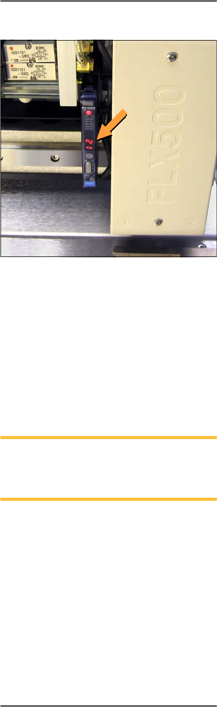
Figure 16—PNP Head optic sensor digital display
showing a reading of 12.
The reading on the top surface of the module
should be approximately in the range
1000--2500. If it is too high (>2500), then roughen
the top surface with 400 grit sandpaper. If the
reading is too low ( <1000), then polish the top
surface with fine emery cloth.
If the reading on the fiducial slot is not within
the allowed range (0– 500), gently blow out the
fiducial slot with clean, dry, compressed air.
NOTE: When running the Fiducial Scan
from the Diagnostic Window, repeatability
on subsequent scans should be ±10 counts.
(One count is 1/100 mm.)
If problems with the fiducial scan continue, see
the on-screen Diagnostics Help, which includes
further diagnostics. You need a PIN to enter the
Diagnostics Windows (Tools button) prior to tap-
ping the Help button.

Data I/O
FLX500 Chptr 3
—30—
Insufficient Vacuum
If you notice insufficient vacuum on the probe
tips (e.g., devices are dropped), perform the Vac-
uum Check: see Check Vacuum on page 19. If
some of the checks fail (red Xs on report when
the details check box is checked) then check that:
• all hose fittings are tight and hoses are not
pinched or clogged.
Perform the probe blowout procedure; see
Maintaining Air Flow on page 16.
• the air filters are not dirty. Replace air filters
if necessary. See Checking Air Filters on page
20.
• the input air to the FLX is at .48-.55 MPa
(70-80 PSI).
If you can’t find the source of the problem, save
the detailed Check Vacuum report and send it to
support@dataio.com.
Failures Picking and Placing
If probes drop devices or fail to pick and place
devices accurately, check the following:
• check for insufficient vacuum; see previous
heading.
• check the Z-Offset; see Calibrating Probe-
Offset on page 15.
• check the module alignment; see Gantry
Movement and Alignment on page 10.