FLX500-maintenance.pdf - 第32页
Data I/O FLX500 Chptr 3 —28— Figur e 15—The bottom of a Pr ogrammer Module allows access to the actuating screws when power to the programmer is unavailable. 3. Slide the Actuator Plate out from the pro- grammer . …

3 … Troubleshooting Actuating a Programmer
—27—
If you are experiencing low throughput during
normal operation, and your PPH when run-
ning the PV-Kit job is . . .
. . . greatly reduced from the original, then contact
Data I/O or your local representative. For contact
information see Customer Support on page 35.
. . . the same as when it was new, then you can gen-
erally eliminate suspected problems with the
FLX500. The problem may have to do with your
device, algorithm, job file, etc. (things related to
device or job file).
Actuating a Programmer
Without Power
If you have a Programmer Module that is not
installed on an FLX500 and still has a Socket
Adapter in it, the Actuator Plate should be in the
up position for removal of the Socket Adapter. If
it is in the down position, you can remove the
adapter by manually actuating the Actuator
Plate to the up (sockets closed) position.
To manually actuate the plate on a programmer
without power:
1. Lay the Programmer Module on its side to
access the bottom.
2. With a flat screwdriver, rotate the actuator
screw shown in Figure 15 as many revolu-
tions as necessary to free the Actuator Plate
so it can be slid out.

Data I/O
FLX500 Chptr 3
—28—
Figure 15—The bottom of a Programmer Module
allows access to the actuating screws when power to
the programmer is unavailable.
3. Slide the Actuator Plate out from the pro-
grammer.
4. Remove the Socket Adapter in the usual
way. For help removing the adapter, see the
on-screen Help.
Fiducial Scan Errors
If the FLX500 fails to program after the PNP Head
scans the modules, there may be a problem with
the scanning.
NOTE: For accurate scanning, the fiducials
and sensors must be clean and the FLX cover
must be closed. For cleaning instructions,
see Cleaning the Fiducials and Sensors on
page 12.
For this check only, open the cover and view the
PNP Head optic sensor during scanning. The
digital display should read:
• 1000+ on the top surface (shiny, metal) of the
module
• 0 — 500 within the fiducial slot
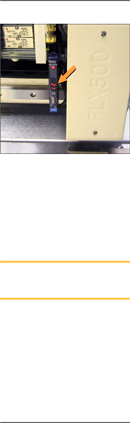
3 … Troubleshooting Fiducial Scan Errors
—29—
Figure 16—PNP Head optic sensor digital display
showing a reading of 12.
The reading on the top surface of the module
should be approximately in the range
1000--2500. If it is too high (>2500), then roughen
the top surface with 400 grit sandpaper. If the
reading is too low ( <1000), then polish the top
surface with fine emery cloth.
If the reading on the fiducial slot is not within
the allowed range (0– 500), gently blow out the
fiducial slot with clean, dry, compressed air.
NOTE: When running the Fiducial Scan
from the Diagnostic Window, repeatability
on subsequent scans should be ±10 counts.
(One count is 1/100 mm.)
If problems with the fiducial scan continue, see
the on-screen Diagnostics Help, which includes
further diagnostics. You need a PIN to enter the
Diagnostics Windows (Tools button) prior to tap-
ping the Help button.