FLX500-maintenance.pdf - 第20页
Data I/O FLX500 Chptr 2 —16— Figure 7—The Alignment Window within the Diag- nostics tools offers pr obe offset calibrations. Cleaning the Cover and Work Surface T ools Re quired: • isopropyl alcohol and cloth Light…

2 … Periodic Maintenance Monthly or Quarterly
—15—
Monthly or Quarterly Main-
tenance
• Calibrating Probe-Offset
• Cleaning the Cover and Work Surface
• Maintaining Air Flow
Calibrating Probe-Offset
Recalibrating the offset of the probes includes
the Z-Offset (the height difference between the
two probes). Do this procedure each month and:
• after replacing probe tips
• after any repair on the PNP Head or probes
• if you are experiencing problems picking
devices, especially with probe two.
To recalibrate the offset, see the on-screen Help
for the Diagnostics –Alignment Window.
NOTE: Recalibration takes 5 to 7 minutes to
complete, a Calibration Tool, a 4 mm hex key
(Allen wrench), and a PIN (Personal Identi-
fication Number) to access the Diagnostics
Windows (after tapping the Tools button).
Figure 6—The FLX programmer calibration tool is
Part Number 615-7054 (and came with your 2009
or later FLX500).
Data I/O
FLX500 Chptr 2
—16—
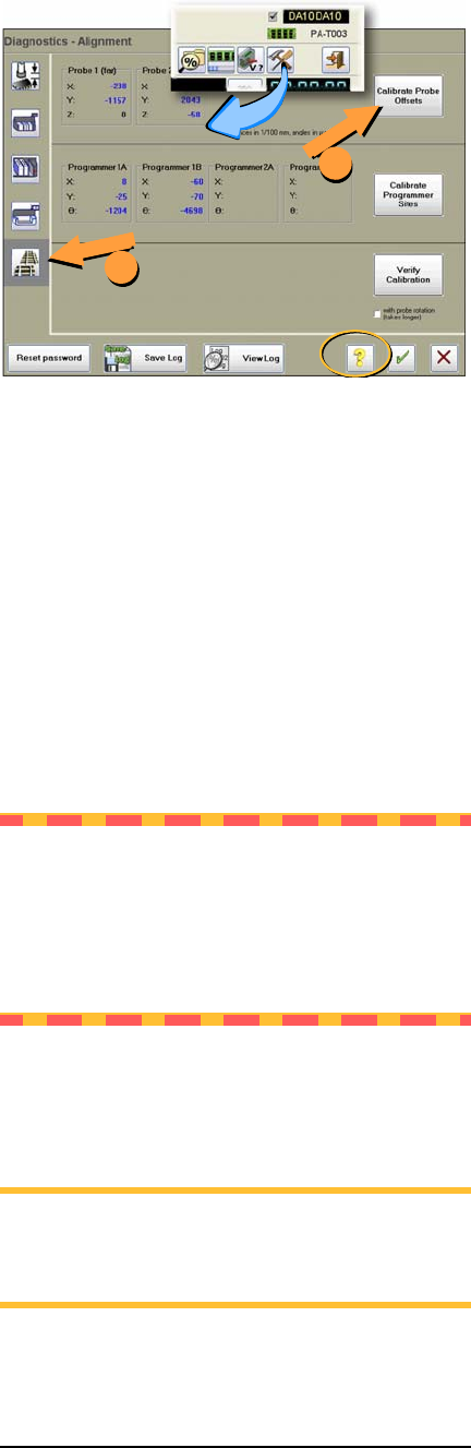
Figure 7—The Alignment Window within the Diag-
nostics tools offers probe offset calibrations.
Cleaning the Cover and Work
Surface
Tools Required:
• isopropyl alcohol and cloth
Lightly clean the cover and work surface with
isopropyl alcohol on a cloth every four months.
CAUTION: Do not use solvents such as
acetone, lacquer thinner, mineral spirits, or
any type of abrasive compound on the cover.
Use of these products, or excessive pressure,
will damage the surface, reduce visibility and
remove the ESD dissipative properties.
Maintaining Air Flow
NOTE: Shop air to the FLX should be
.48-.55 MPa @ .028 M
3
/min. (70-80 PSI @
1.0 cfm).
1
2
2 … Periodic Maintenance Monthly or Quarterly
—17—
Perform the following probe blowout procedure
quarterly and at times when pick failures occur
often. This interval is dependent on the amount
of machine use and air quality. Adjust your inter-
val as required. For example, preventing the
probes from drawing in air for long periods of
non-use—using Automatic Air Management
(see the on-screen Diagnostic Help) or manually
shutting air off to the probes while idle—can
reduce the need to perform this blowout proce-
dure as often.
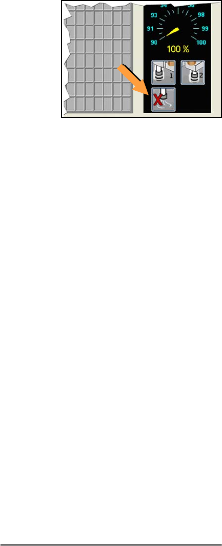
Figure 8—Probe air-shut-off buttons on the Run
Window.
Probe Blowout Procedure
Tools Required:
• Standard (flat) screwdriver
• tape or method to mark tubes
• compressed air, clean and dry, .48-.62
MPa (70-90 PSI)
1. Stop the job if applicable. For instructions
see the on-screen Help.
2. Switch power off.
3. Push the E-Stop
Blow Out the Probes
4. Open the cover and move the PNP Head
close for access to its far side.
5. Locate the two clear tubes just to the far side
of the head cover, plugged into barbed fit-
tings. With a small flat screwdriver pry each
tube off its fitting, marking which tube goes
to which fitting.