NR_Mechanischer_Stopper.pdf - 第157页
Assembly Instructions PCB Stopper Single Conveyor SIPLACE S-27HM / HS-60 / D4 / D 3 / HF- / X-Series Edition 06/2007 157 13.2.2 Inst allation of the stoppers The following point s are described for the dual conveyor , bu…
Assembly Instructions PCB Stopper Single Conveyor SIPLACE S-27HM / HS-60 / D4 / D3 / HF- / X-Series
Edition 06/2007
156
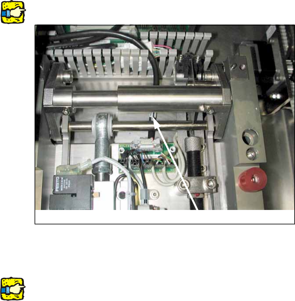
O Connect the control cable and the compressed air hose to the lifting table again.
13
13
When doing so make sure that the cable is laid beneath the mechanical system.
13
Fig. 132
O Install the cover over the lifting table board.
13
For dual conveyor only: 13
Remove all parts from the machine that are not permanently attached to it (tools and other parts
required for the installation).
Don't forget the nozzle changer and the machine zero point. 13
O Switch the machine on again at the main switch.
O Carry out a reference run and change the conveyor track setting from 50 mm to maximum con-
veyor width.
O Shut down the operating system and switch off the placement machine at the main switch.
Cable
Assembly Instructions PCB Stopper Single Conveyor SIPLACE S-27HM / HS-60 / D4 / D3 / HF- / X-Series
Edition 06/2007
157
13.2.2 Installation of the stoppers
The following points are described for the dual conveyor, but apply similarly to the single
conveyor: 13
Caution: Before the stopper is mounted in the machine, it should be adjusted with the guide strip
and the shims. Care should be taken to ensure that the stopper is not too loose or too tight. The
graduation of the shims is 0.1mm.
(See also Fig. 209, page - 232.)
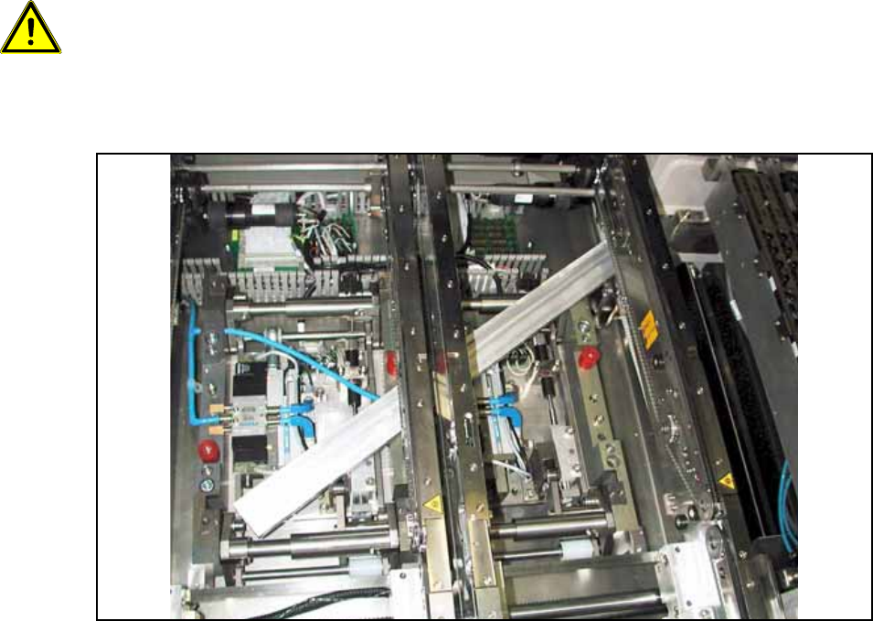
O Push the guide strip into the conveyor from outside.
Fig. 133 Guide rail
O Thread the stopper for PA2 Conveyor track 2 onto the guide strip. The trailing cables of this
stopper must have a low spacer.
Assembly Instructions PCB Stopper Single Conveyor SIPLACE S-27HM / HS-60 / D4 / D3 / HF- / X-Series
Edition 06/2007
158
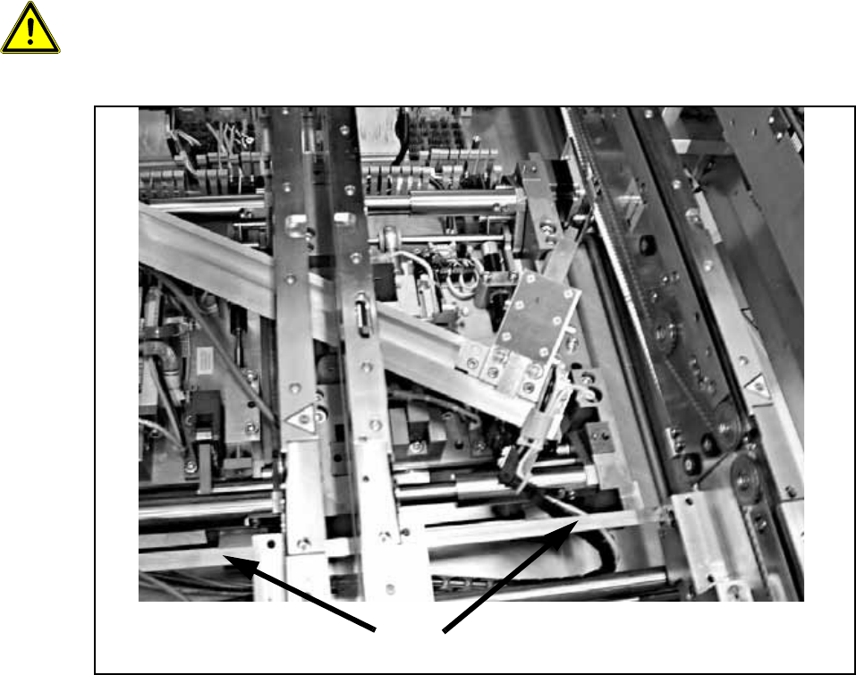
O Insert the two stopper units between the two side sections into the guide slot of the guide strip.
13
When installing the stopper be careful not to damage the terminal strip of the width adjustment for
the PCB conveyor. 13
13
Fig. 134
Terminal strip of width adjustment for PCB conveyor