NR_Mechanischer_Stopper.pdf - 第230页
Assembly Instructions PCB Stopper Sin gle Conveyor SIPLACE S-27HM / HS-60 / D4 / D3 / HF- / X-Series Edition 06/2007 230
Assembly Instructions PCB Stopper Single Conveyor SIPLACE S-27HM / HS-60 / D4 / D3 / HF- / X-Series << >
Edition 06/2007 << >
229
18.1 Testing individual functions
O Take a PCB and move it through each track of the PCB conveyor with the PCB conveyor func-
tions.
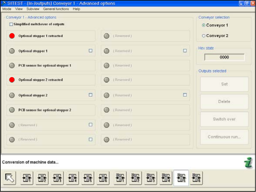
O You can check the status of the stopper in the window "Input/Output Functions 5".
Fig. 206
O Calibrate the machine zero point and the position of the nozzle changer (HS-60) also if neces-
sary.
O Finally, the PCB reference corner position needs to be recalibrated for each stop position.
18
18
Assembly Instructions PCB Stopper Single Conveyor SIPLACE S-27HM / HS-60 / D4 / D3 / HF- / X-Series
Edition 06/2007
230
Assembly Instructions PCB Stopper Single Conveyor SIPLACE S-27HM / HS-60 / D4 / D3 / HF- / X-Series
Edition 06/2007
231
19 General troubleshooting
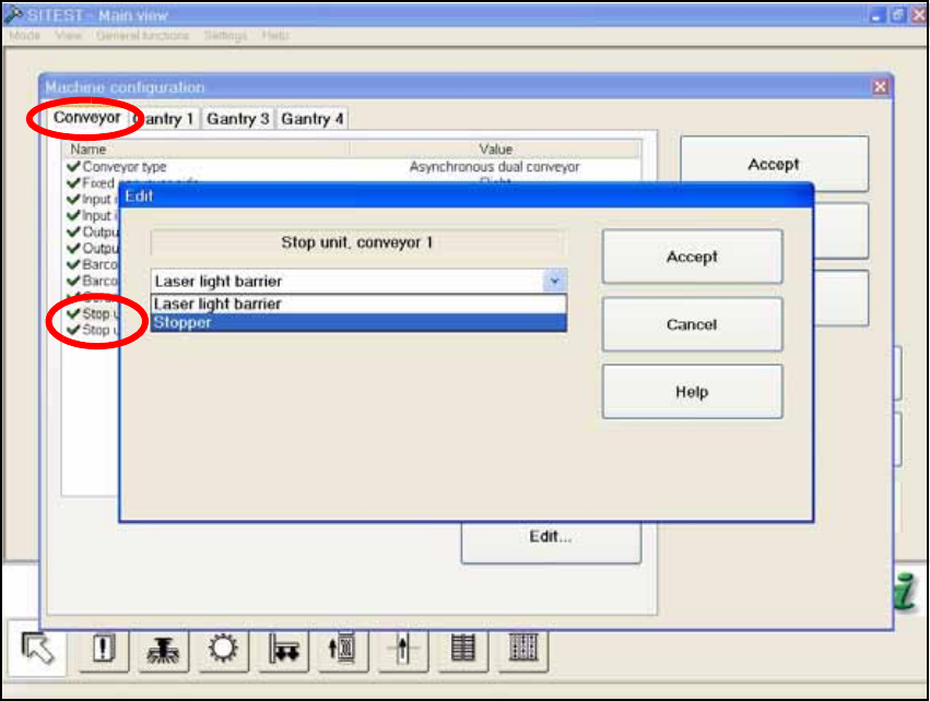
If a stopper fails, generally a conveyor track can also be switched over to laser light barrier. The
mechanical stopper on the other track remains active and component placement can continue on
both conveyor tracks. 19
Fig. 207