NR_Mechanischer_Stopper.pdf - 第216页
Assembly Instructions PCB Stopper Sin gle Conveyor SIPLACE S-27HM / HS-60 / D4 / D3 / HF- / X-Series Edition 06/2007 216 O S tow the remaining cables in the cable duct s. Fig. 197 Conversion bo ard for conveyor track 2 C…
Assembly Instructions PCB Stopper Single Conveyor SIPLACE S-27HM / HS-60 / D4 / D3 / HF- / X-Series
Edition 06/2007
215
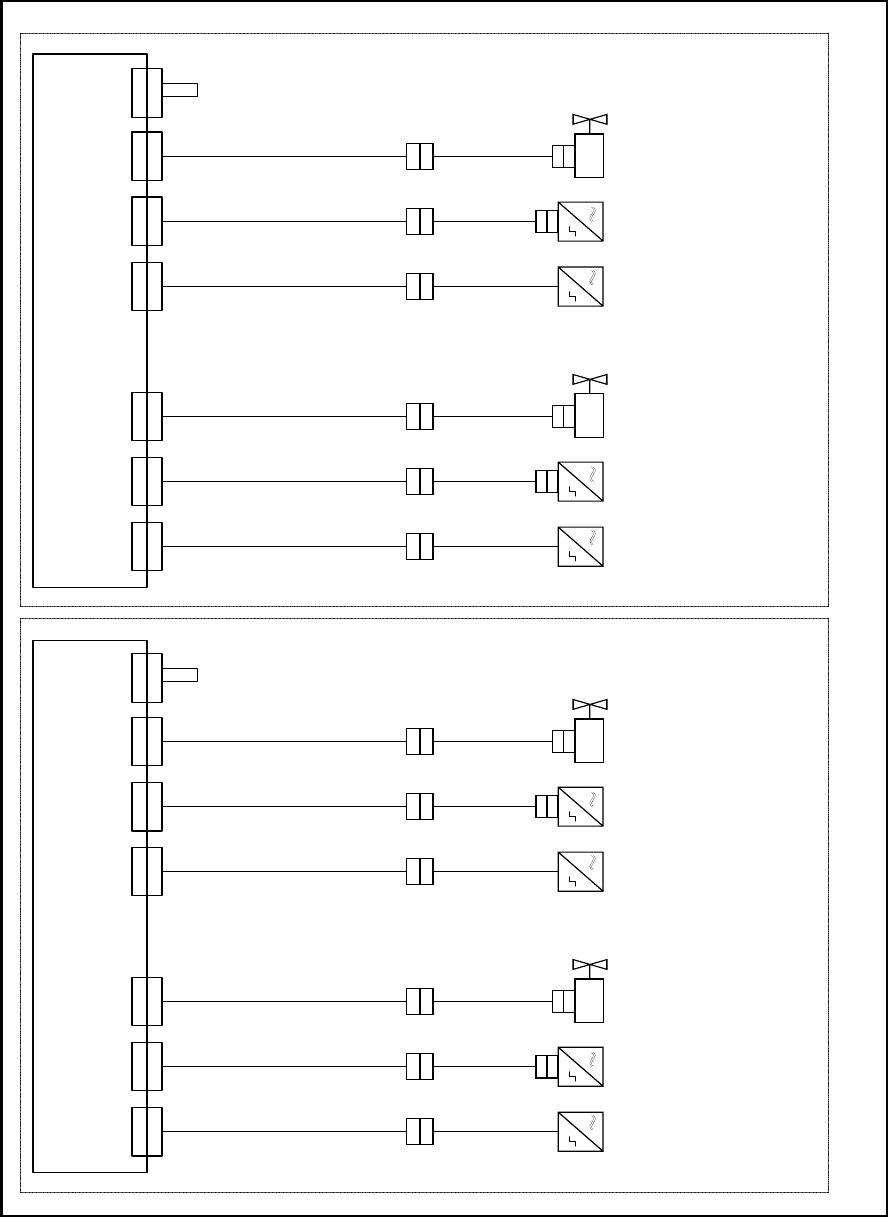
Fig. 196 Cabling of optional PCB stopper HS-60/D4/HF-Series/X-Series
X 1 7
U m s e t z p l a t i n e T r a n s p o r t , S p u r 1
C o n v e r s i o n b o a r d c o n v e y o r , l a n e 1
0 0 3 5 9 4 2 5 - x x ( k t )
X 1 7 k t
0 3 0 3 7 1 9 4 - x x
0 3 0 3 7 1 9 6 - x x
T r a n s p o r t s p u r 1 / C o n v e y o r l a n e 1 T r a n s p o r t s p u r 2 ( n u r b e i D o p p e l t r a n s p o r t ) / C o n v e y o r l a n e 2 ( d u a l c o n v e y o r o n l y )
0 3 0 3 7 2 0 0 - x x
X 1 3
X 1 3 k t
X 3 0
X 3 0 k t
X 1 8 k t
0 3 0 3 7 1 9 5 - x x
0 3 0 3 7 1 9 7 - x x
0 3 0 3 7 2 0 1 - x x
X 1 5 k tX 3 3 k t
B e s t ü c k b e r e i c h 1
P r o c e s s i n g a r e a 1
B e s t ü c k b e r e i c h 2
P r o c e s s i n g a r e a 2
X 1 8X 1 5X 3 3 X 1 7
U m s e t z p l a t i n e T r a n s p o r t , S p u r 2
C o n v e r s i o n b o a r d c o n v e y o r , l a n e 2
0 0 3 5 9 4 2 5 - x x ( k u )
X 1 7 k u
0 3 0 3 7 1 9 4 - x x
0 3 0 3 7 1 9 6 - x x
0 3 0 3 7 2 0 0 - x x
X 1 3
X 1 3 k u
X 3 0
X 3 0 k u
X 1 8 k u
0 3 0 3 7 1 9 5 - x x
0 3 0 3 7 1 9 7 - x x
0 3 0 3 7 2 0 1 - x x
X 1 5 k uX 3 3 k u
X 1 8X 1 5X 3 3
X 6
X 6 k t
X 6
X 6 k u
0 3 0 3 7 2 0 4 - x x
0 3 0 3 7 2 0 4 - x x
X a
X a
X b
X b
X a
X a
X b
X b
X a
X a
X b
X b
X a
X a
X b
X b
0 3 0 5 3 5 6 3 - x x
0 3 0 5 3 5 6 2 - x x
0 3 0 5 3 5 6 3 - x x
0 3 0 5 3 5 6 2 - x x
0 3 0 5 3 5 6 3 - x x
0 3 0 5 3 5 6 2 - x x
0 3 0 5 3 5 6 3 - x x
0 3 0 5 3 5 6 2 - x x
X c
X c X c X c
X d
X d
X d
X d
0 3 0 5 6 1 5 7 - x x
0 3 0 5 6 1 5 7 - x x
X d
X d
0 3 0 5 6 1 5 7 - x x
X d
X d
0 3 0 5 6 1 5 7 - x x
B e s t ü c k b e r e i c h 1
P r o c e s s i n g a r e a 1
B e s t ü c k b e r e i c h 2
P r o c e s s i n g a r e a 2
S o n a r b e r o
S o n a r s e n s o r
0 3 0 3 2 8 7 3 - x x
S e n s o r u n t e r e P o s i t i o n
S e n s o r l o w e r p o s i t i o n
V e n t i l
V a l v e
S o n a r b e r o
S o n a
r s e n s o r
0 3 0 3 2 8 7 3 - x x
S e n s o r u n t e r e P o s i t i o n
S e n s o r l o w e r p o s i t i o n
V e n t i l
V a l v e
S o n a r b e r o
S o n a r s e n s o r
0 3 0 3 2
8 7 3 - x x
S e n s o r u n t e r e P o s i t i o n
S e n s o r l o w e r p o s i t i o n
V e n t i l
V a l v e
S o n a r b e r o
S o n a r s e n s o r
0 3 0 3 2 8 7 3 - x x
S e n s o r
u n t e r e P o s i t i o n
S e n s o r l o w e r p o s i t i o n
V e n t i l
V a l v e
C o d i e r b r ü c k e " S t o p p e r S p u r 1 e i n g e b a u t "
C o d i n g j u m p e r " S t o p p e r l a n e 1 i n s t a l l e d "
C o d i e r b r ü c k e " S t o p p e r
S p u r 1 e i n g e b a u t "
C o d i n g j u m p e r " S t o p p e r l a n e 1 i n s t a l l e d "
Assembly Instructions PCB Stopper Single Conveyor SIPLACE S-27HM / HS-60 / D4 / D3 / HF- / X-Series
Edition 06/2007
216
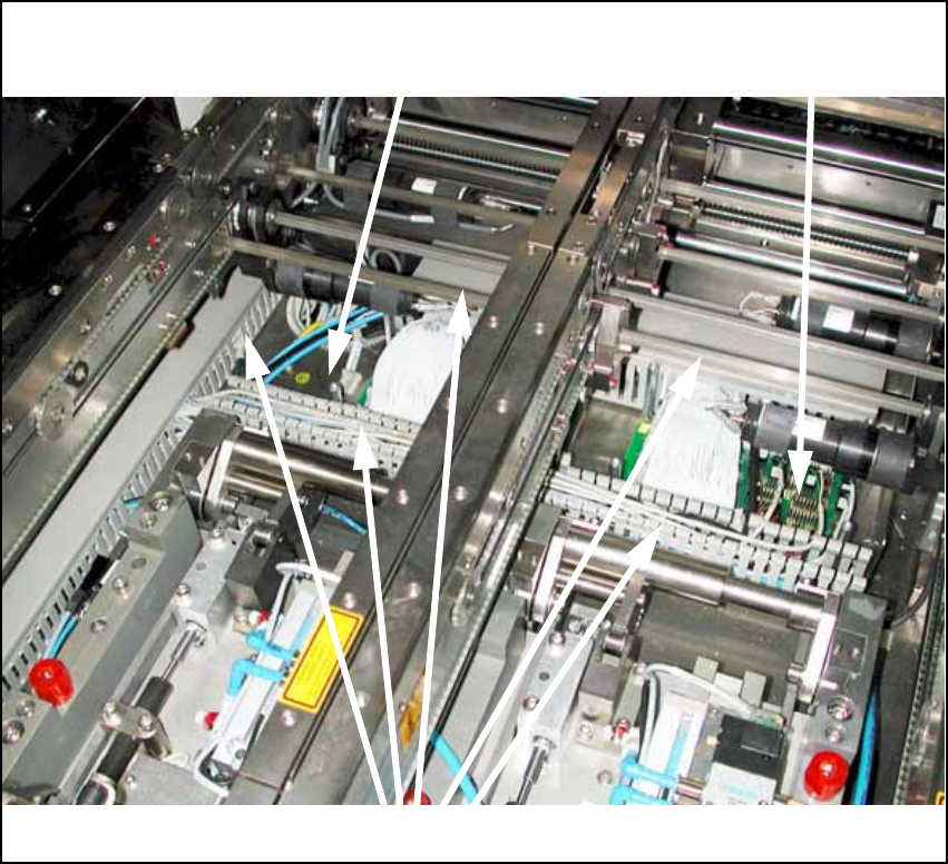
O Stow the remaining cables in the cable ducts.
Fig. 197
Conversion board for
conveyor track 2
Conversion board for
conveyor track 1
Cable ducts

Assembly Instructions PCB Stopper Single Conveyor SIPLACE S-27HM / HS-60 / D4 / D3 / HF- / X-Series
Edition 06/2007
217
15.3.3.3 Pneumatic tubing
Note:
Lay all the hoses so that there are no kinks.
Placement area 1 15
O Take the 2-way distributor with the short feed line and plug it onto the free connection on the
solenoid valve.
Note:
Shorten the hoses if necessary.
O If you have a single conveyor machine, remove the 2nd hose and replace it with a blind plug.
O Repeat the process for the 2nd solenoid valve.
O If necessary, fix the hoses in position with self-adhesive cable clamps and cable ties.
Placement area 2 15
O Take the 2-way distributor that you previously pushed toward the conversion board from PA1,
and lay it in the cable ducts to the solenoid valves in placement area 2.
O Plug the hose coming from the 2-way distributor onto the free connection on the solenoid valve.
Note:
Shorten the hoses if necessary.
O If you have a single conveyor machine, remove the 2nd hose and replace it with a blind plug.
O Repeat the process for the 2nd solenoid valve.
O If necessary, fix the hoses in position with self-adhesive cable clamps and cable ties.