NR_Mechanischer_Stopper.pdf - 第196页
Assembly Instructions PCB Stopper Sin gle Conveyor SIPLACE S-27HM / HS-60 / D4 / D3 / HF- / X-Series Edition 06/2007 196 14.4 Pneumatics plan S-27HM Fig. 176 Pneumatics plan S-27HM
Assembly Instructions PCB Stopper Single Conveyor SIPLACE S-27HM / HS-60 / D4 / D3 / HF- / X-Series
Edition 06/2007
195
O Fit all the cable duct covers.
O Fit the cover of the conversion board.
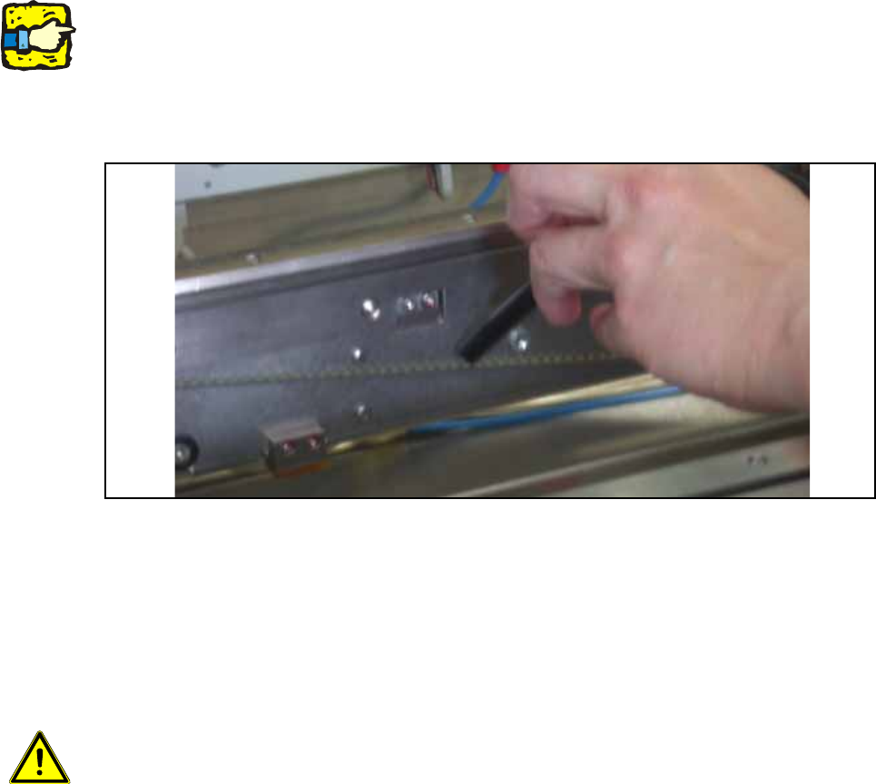
O Install the motor in conveyor track 2 again (3 hexagon screws).
Note the different screw lengths (short at the top, long at the bottom) and make sure the toothed
belt is correctly seated.
O Check whether the toothed belt has the correct tension of 110 +/- 5 Hz . Correct the tension if
necessary.
Fig. 175 Check belt tension
O Push the shaft back into conveyor track 2 and fit the corresponding shaft fixation on the outside
of the lifting table.
O Install the shortened lifting table plates on the lifting table.
O Dock the changeover tables again.
14
Caution: Crash hazard!
Check whether there are any objects left in the machine! Remove them.
O Switch on the placement machine at the main switch.
O Change to SITEST.
O Perform the settings according to:
"Setting the sonar proximity switches on the stopper" see section 16 on page - 221 14
"Software configuration and testing of the stopper" see section 18 on page - 227 14
14
Assembly Instructions PCB Stopper Single Conveyor SIPLACE S-27HM / HS-60 / D4 / D3 / HF- / X-Series
Edition 06/2007
196
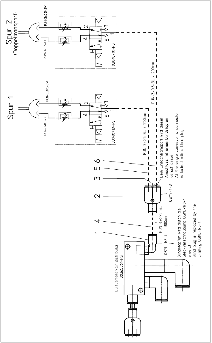
14.4 Pneumatics plan S-27HM
Fig. 176 Pneumatics plan S-27HM

Assembly Instructions PCB Stopper Single Conveyor SIPLACE S-27HM / HS-60 / D4 / D3 / HF- / X-Series
Edition 06/2007
197
15 Retrofitting SIPLACE HF-Series / X-
Series / D3
Caution: Before the stopper is mounted in the machine, it should be adjusted with the guide strip
and the shims. Care should be taken to ensure that the stopper is not too loose or too tight. The
graduation of the shims is 0.1mm.
(See also Fig. 209, page - 232.)
15.1 Preparatory work
O Start with the installation of the stoppers in placement area 1.
O Change over to the SITEST.
O Select "Conveyor" and "Conveyor width".
O Adjust the conveyor width to maximum.
O Undock the component trolley onto locations 1 and 3.
O Shut down the operating system and switch off the placement machine at the main switch.
O Remove all the lifting table plates.
O Remove the cover of the conversion board.
O Detach the metal cover of the cable duct.
O Remove the cable duct covers.