NR_Mechanischer_Stopper.pdf - 第197页
Assembly Instructions PCB Stopper Single Conveyor SIPLACE S-27HM / HS-60 / D4 / D 3 / HF- / X-Series Edition 06/2007 197 15 Retrofitting SIPLACE HF-Series / X- Series / D3 Caution: Before the stopper is mou nted in the m…
Assembly Instructions PCB Stopper Single Conveyor SIPLACE S-27HM / HS-60 / D4 / D3 / HF- / X-Series
Edition 06/2007
196
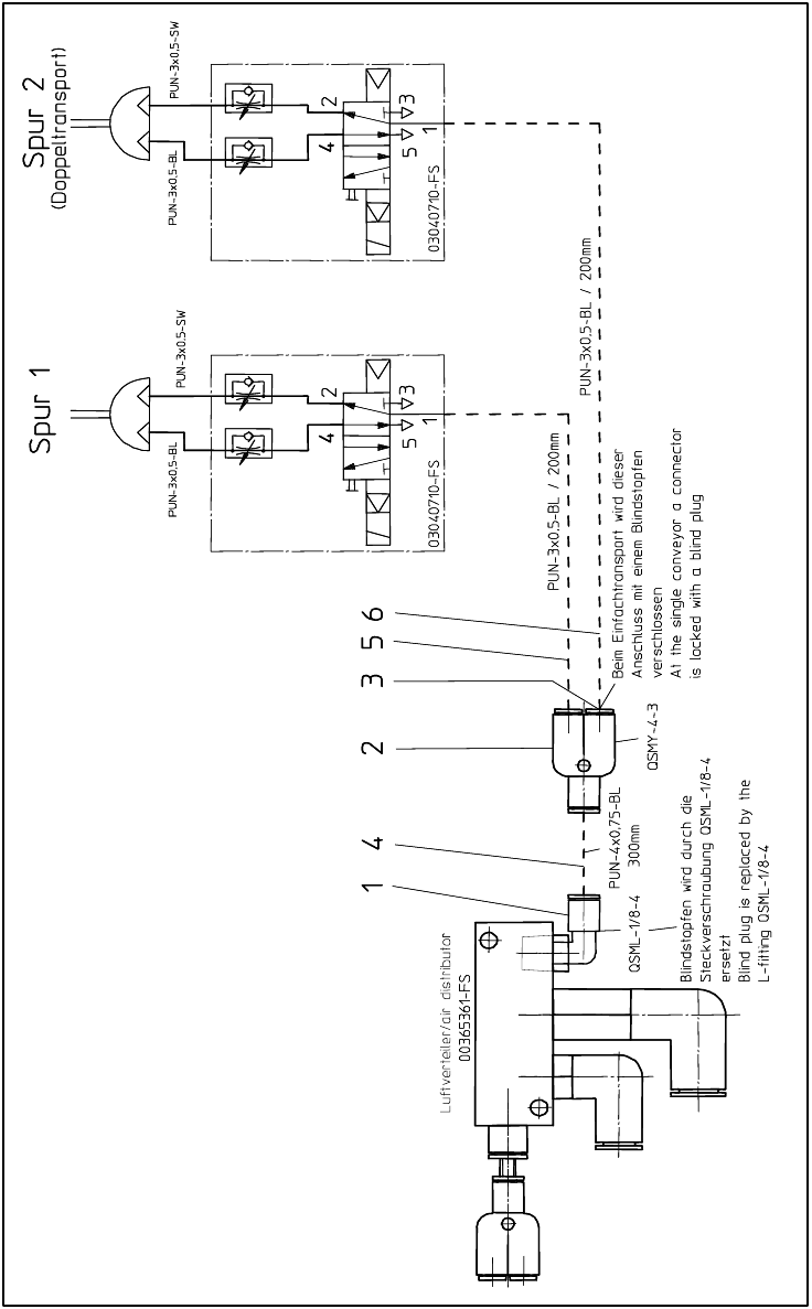
14.4 Pneumatics plan S-27HM
Fig. 176 Pneumatics plan S-27HM

Assembly Instructions PCB Stopper Single Conveyor SIPLACE S-27HM / HS-60 / D4 / D3 / HF- / X-Series
Edition 06/2007
197
15 Retrofitting SIPLACE HF-Series / X-
Series / D3
Caution: Before the stopper is mounted in the machine, it should be adjusted with the guide strip
and the shims. Care should be taken to ensure that the stopper is not too loose or too tight. The
graduation of the shims is 0.1mm.
(See also Fig. 209, page - 232.)
15.1 Preparatory work
O Start with the installation of the stoppers in placement area 1.
O Change over to the SITEST.
O Select "Conveyor" and "Conveyor width".
O Adjust the conveyor width to maximum.
O Undock the component trolley onto locations 1 and 3.
O Shut down the operating system and switch off the placement machine at the main switch.
O Remove all the lifting table plates.
O Remove the cover of the conversion board.
O Detach the metal cover of the cable duct.
O Remove the cable duct covers.
Assembly Instructions PCB Stopper Single Conveyor SIPLACE S-27HM / HS-60 / D4 / D3 / HF- / X-Series
Edition 06/2007
198
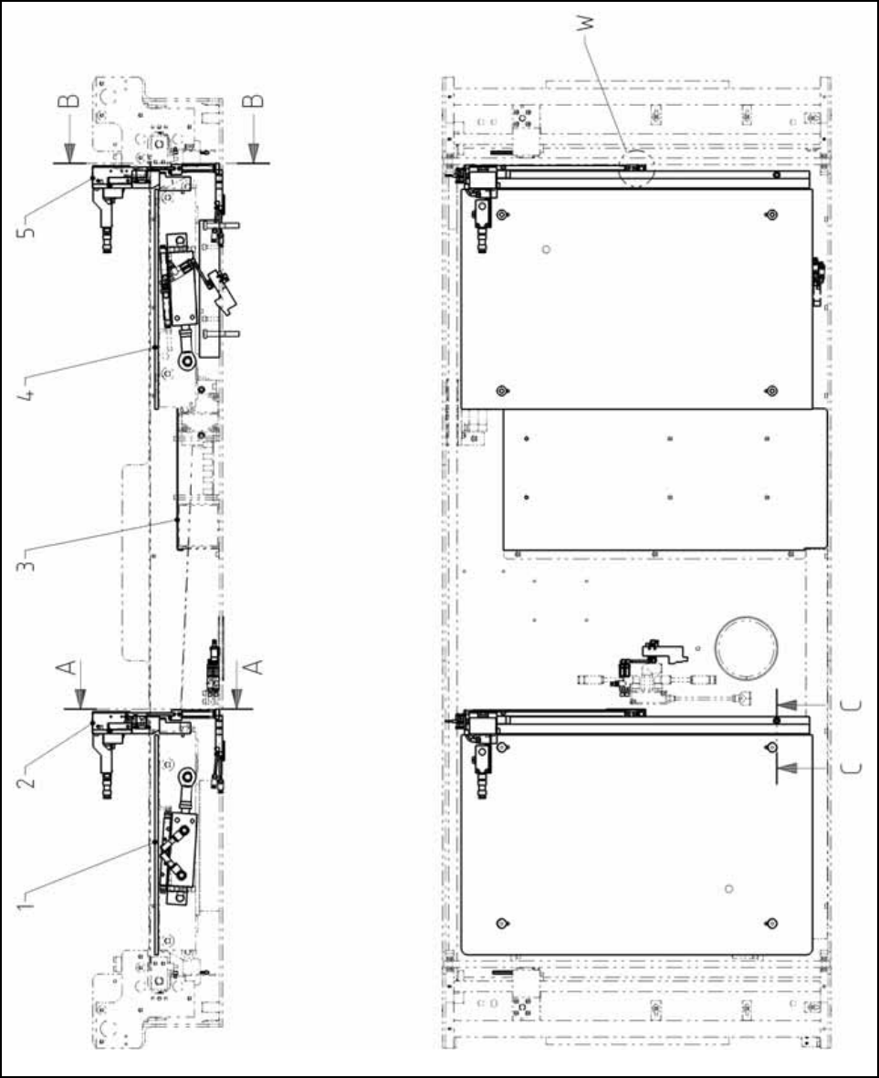
15.1.1 Gesamtübersicht
Fig. 177 Overview HF-/X-Series/D3 (Fig. 1) Single conveyor