NR_Mechanischer_Stopper.pdf - 第199页
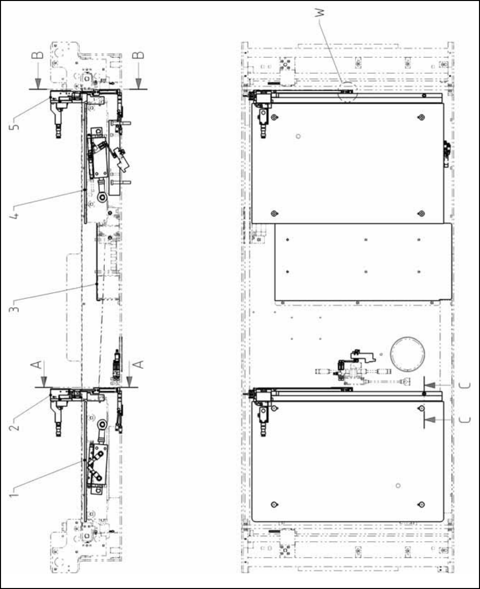
Assembly Instructions PCB Stopper Single Conveyor SIPLACE S-27HM / HS-60 / D4 / D 3 / HF- / X-Series Edition 06/2007 199 Fig. 178 Overview HF-/X-Series /D3 (Fig. 2) Single conveyor Legend (Figs. 1 and 2) Single conveyor …
Assembly Instructions PCB Stopper Single Conveyor SIPLACE S-27HM / HS-60 / D4 / D3 / HF- / X-Series
Edition 06/2007
198
15.1.1 Gesamtübersicht
Fig. 177 Overview HF-/X-Series/D3 (Fig. 1) Single conveyor
Assembly Instructions PCB Stopper Single Conveyor SIPLACE S-27HM / HS-60 / D4 / D3 / HF- / X-Series
Edition 06/2007
199
Fig. 178 Overview HF-/X-Series/D3 (Fig. 2) Single conveyor
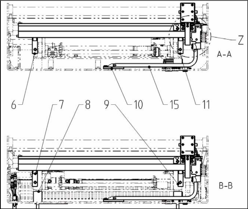
Legend (Figs. 1 and 2) Single conveyor 15
1 Lifting table plate Option PCB Stopper
SC
8 Energy chain E04
2 Basic unit stopper HS/HF PA1 9 Guide strip HF
3 Basic unit stopper HS/HF PA2 10 ISO 4762 - M5 x 20-8.8, chem. nickel
plat.
4 Holder for guide strip PA1 HF 11 ISO 4762 - M4 x 40-8.8, chem. nickel
plat.
5 Holder for guide strip PA2 HF 12 DIN EN ISO 7380-M3 x 6-A2
6 Distance block for energy chain, compl. 13 Energy chain holder
7 Distance block for energy chain, compl. 14 ISO 4032 - M3-8
Assembly Instructions PCB Stopper Single Conveyor SIPLACE S-27HM / HS-60 / D4 / D3 / HF- / X-Series
Edition 06/2007
200
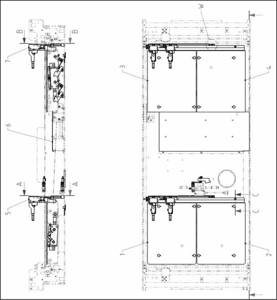
Fig. 179 Overview HF-/X-Series/D3 (Fig. 3) Dual conveyor