NR_Mechanischer_Stopper.pdf - 第161页
Assembly Instructions PCB Stopper Single Conveyor SIPLACE S-27HM / HS-60 / D4 / D 3 / HF- / X-Series Edition 06/2007 161 O Push the guide rail as far as possible into co nveyor track 2. Now push the stopper P A2 of con- …
Assembly Instructions PCB Stopper Single Conveyor SIPLACE S-27HM / HS-60 / D4 / D3 / HF- / X-Series
Edition 06/2007
160
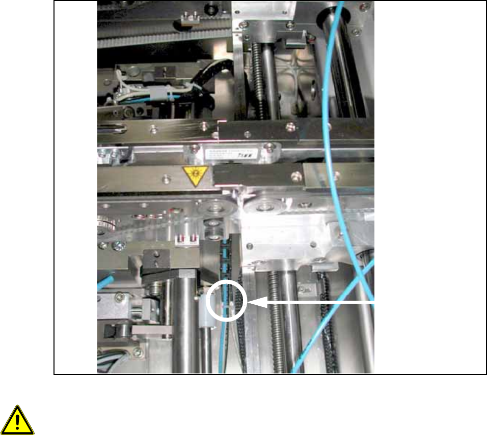
Fig. 136
13
Caution, crash hazard:
It is essential to ensure that the stopper and the trailing cables do not collide with the width adjust-
ment or its conveyor belt. 13
The stopper must subsequently move freely over the entire conveyor width, and the trailing cables
must not tilt to the side. 13
13
Stick here
Holder
Trailing cables
Assembly Instructions PCB Stopper Single Conveyor SIPLACE S-27HM / HS-60 / D4 / D3 / HF- / X-Series
Edition 06/2007
161
O Push the guide rail as far as possible into conveyor track 2. Now push the stopper PA2 of con-
veyor track 1 onto the guide rail.
Be careful not to damage the sliding guides when pushing onto the guide rail!
The trailing cables of this stopper must have a high spacer.
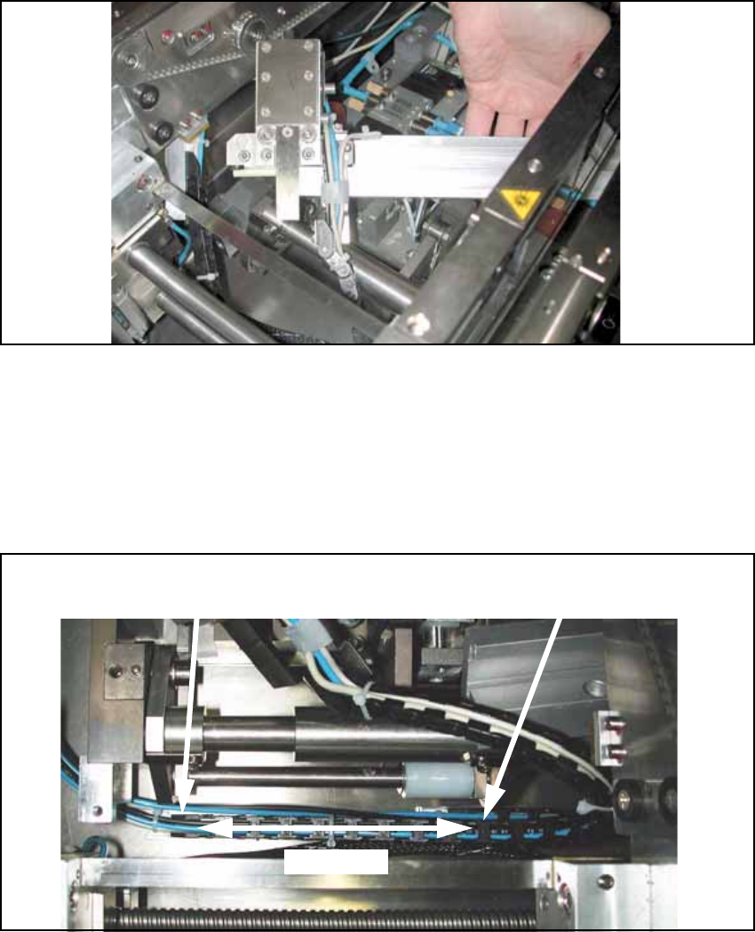
Fig. 137
O Using the prepared adhesive tape, stick the spacer of the trailing cables onto the mounting tub
at the height of the first conveyor side parallel to the width adjustment in such a way that the
trailing cables are vertical to the mounting tub when the guide rail is installed.
The stopper must be able to slide over the entire conveyor width.
The trailing cable must run exactly on the trailing cable of the stopper in conveyor track 2 and
must not tilt to the side.
Fig. 138
The distance between the two distance blocks should be approx. 100 mm. 13
Position for trailing cable holder,
conveyor track 1 in DC or SC
Position for trailing cable
holder, conveyor track 2
100 mm
Assembly Instructions PCB Stopper Single Conveyor SIPLACE S-27HM / HS-60 / D4 / D3 / HF- / X-Series
Edition 06/2007
162
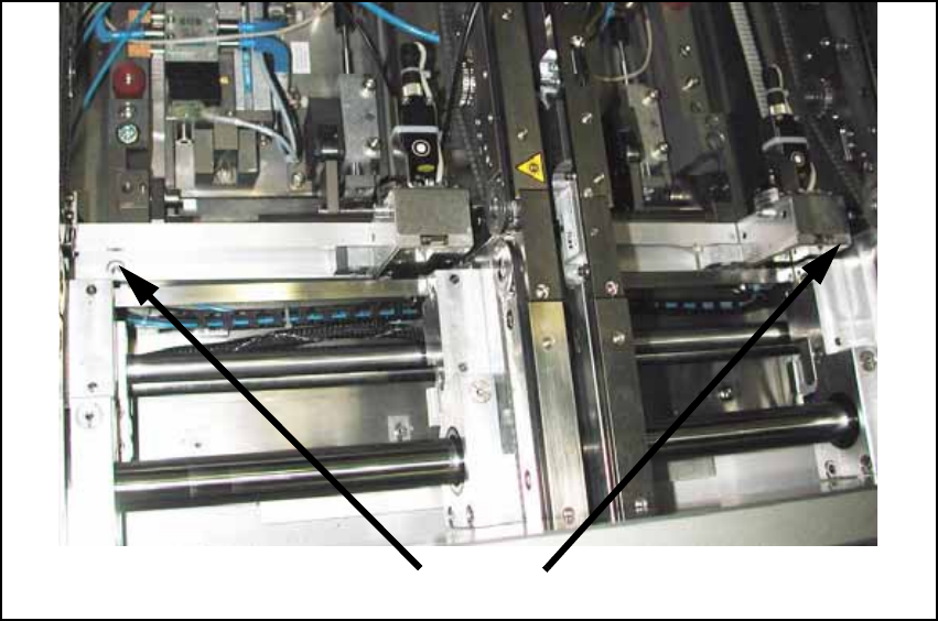
O Affix the guide strip to the holders with two cylinder head bolts with hexagon socket head
M5 x 20-DIN 912.
Fig. 139
O Check that the stoppers can move freely across the entire conveyor width and do not impede
the width adjustment of the conveyor in any way.
Cable laying and wiring are described in a later section for functional reasons. 13
13
Screws