NR_Mechanischer_Stopper.pdf - 第211页
Assembly Instructions PCB Stopper Single Conveyor SIPLACE S-27HM / HS-60 / D4 / D 3 / HF- / X-Series Edition 06/2007 211 15.3.3 Laying cables and pneumatic tubing 15.3.3.1 Complete overview Fig. 192 Cable laying HF-/X-Se…
Assembly Instructions PCB Stopper Single Conveyor SIPLACE S-27HM / HS-60 / D4 / D3 / HF- / X-Series
Edition 06/2007
210
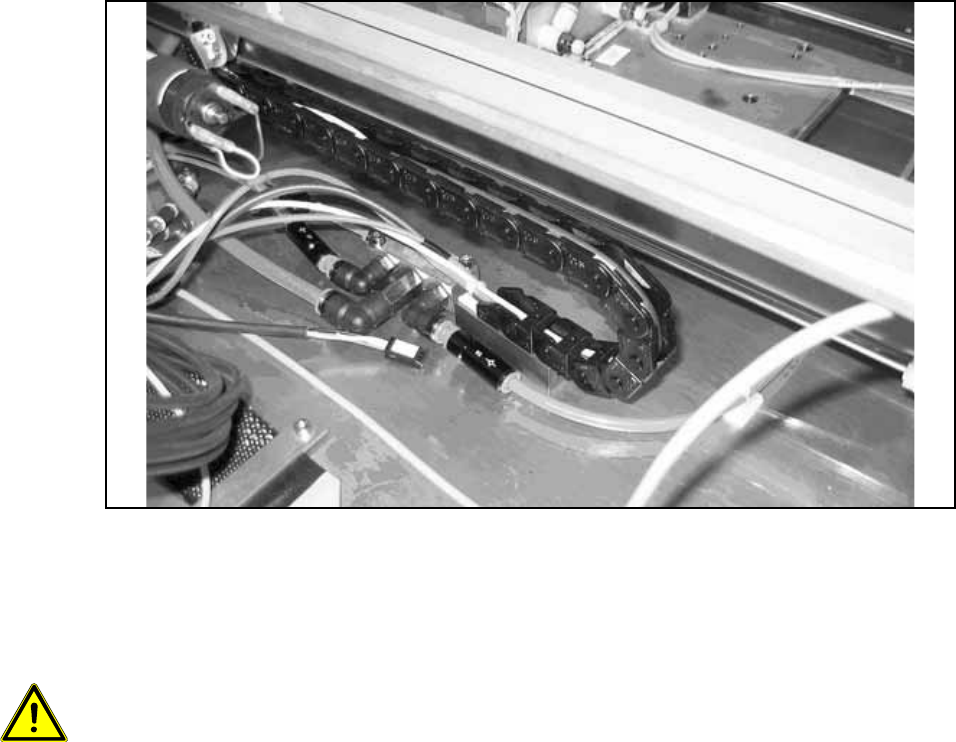
O For a single conveyor, stick the distance block onto the position of conveyor track 1. The stop-
per must be able to slide over the entire conveyor width. The distance block stuck on the floor
of the mounting tub must be positioned so that the trailing cables run parallel to the guide strip
of the stopper. If other cables prevent this, they must be repositioned.
Fig. 191
O Attach the guide strip to the holders with two cylinder head bolts (hexagon socket head
M5 x 20 DIN 912).
15
Caution, crash hazard:
– It is essential to ensure that the stopper and the trailing cables do not collide with the width
adjustment or its conveyor belt.
– The stoppers must be able to slide over the entire conveyor width.
– The trailing cable of conveyor track 1 must run exactly on the trailing cable of the stopper in
conveyor track 2 and must not tilt to the side.
– The distance between the two distance blocks should be approx. 100 mm.
– The laying of cables and tubing is described in a later section for functional reasons.
Assembly Instructions PCB Stopper Single Conveyor SIPLACE S-27HM / HS-60 / D4 / D3 / HF- / X-Series
Edition 06/2007
211
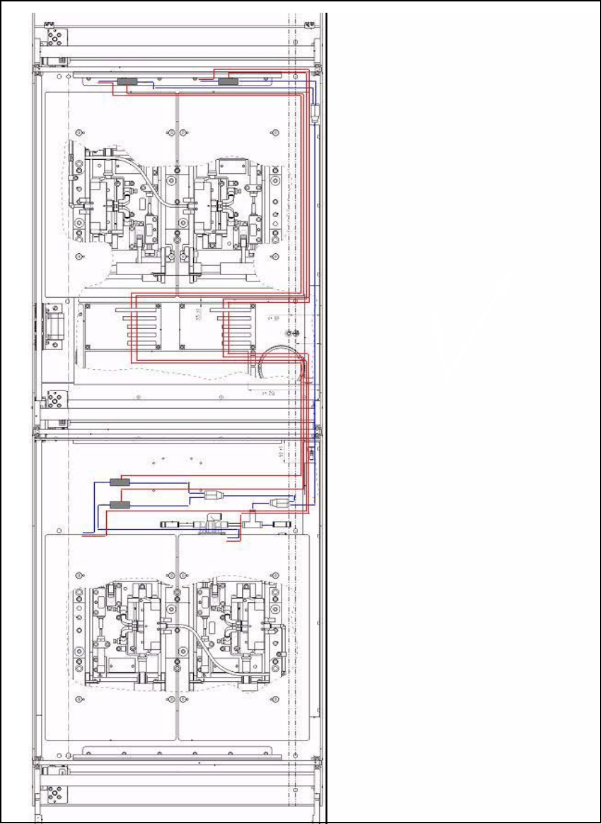
15.3.3 Laying cables and pneumatic tubing
15.3.3.1 Complete overview
Fig. 192 Cable laying HF-/X-Series/D3
Red lines:
Power and data lines 15
Blue lines:
Pneumatic power supply 15
Assembly Instructions PCB Stopper Single Conveyor SIPLACE S-27HM / HS-60 / D4 / D3 / HF- / X-Series
Edition 06/2007
212
15.3.3.2 Cable laying
Placement area 1 15
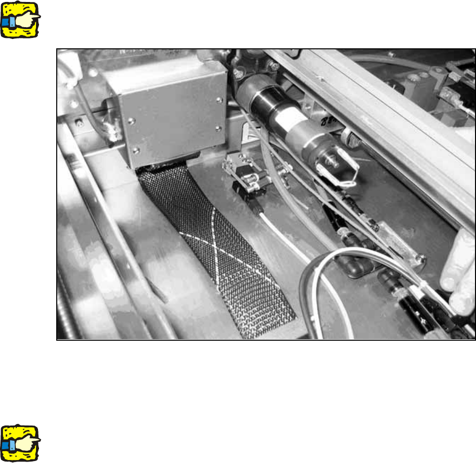
O Position the solenoid valve and the throttles in the conveyor tub so that the functions of the
stopper and the width adjustment are not impaired. Stick the solenoid valve firmly into place as
shown in Fig. 192 on page 211.
Note: The throttles are preset and do not have to be adjusted. Position the throttles so that they
are still accessible, however.
Fig. 193
O Before you start laying the lines, label the connectors with the respective conveyor track.
O Lay the three lines per unit (valve, sonar proximity switch and sensor) to the right hand side of
the machine
Note: When laying the lines take care to ensure that the functions of the stopper and the width
adjustment are not impaired.
O Route the cables and the 2-way distributor with the long feed line through the cable duct to the
conversion board that is in placement area 2.