RX-8_SPE_EN.pdf - 第10页
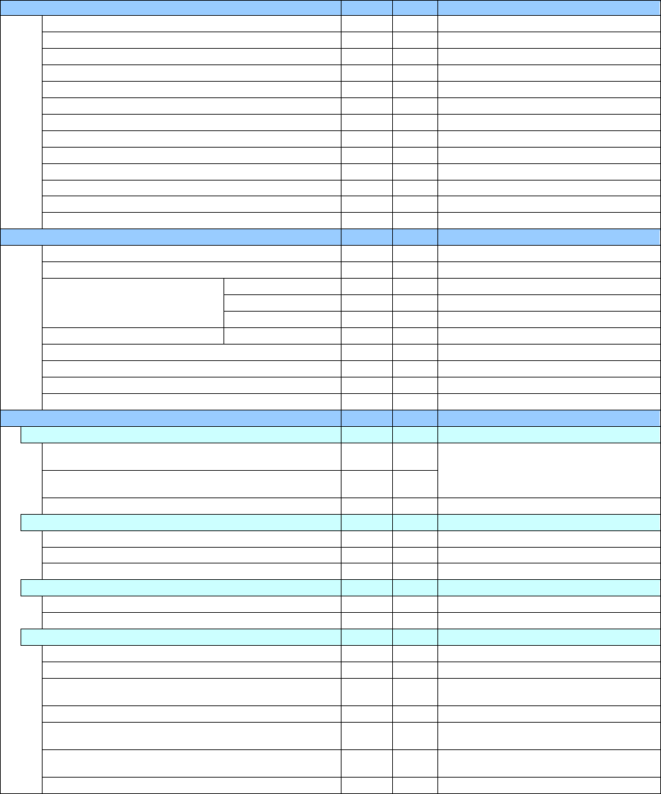
6 4. Specificat ions 4-1 Basic specifications RX -8 Board transfer reference Front referenc e only Supported lang uages Japanese, Eng lish and Chin ese (simplif ied Chines e and tradit ional Chinese) are s witched in rea…
5
Equipment
Feeder float sensor
○ ○
Automatic Tool Change unit (ATC)
○ ○
Large-sized component trash box
- -
Flexible Calibration System (FCS)
○ ○
FCS adjustment jig
● ●
SOT direction inspection table
- -
Component Verification System (CVS)
- ●
P16S nozzle head only
Coplanarity
- -
Fluxer: Type 2 (To be attached on the main unit)
- -
Low load control
- -
High-load control
- -
Offset Placement After Solder Screen-printing
- ●
ADVANCE KIT
- ●
P16S head only / Retrofit only
Production support system
White list type anti-virus software
○ ○
Floor productivity improvement support system
Production support system
IS Lite
- -
IS
- -
JaNets
● ●
After Ver2.05 (RX-7R)
Production control system
IFS-NX
● ●
After Ver1.90 (RX-7R)
Flexline CAD
- -
Component Database for a main unit
● ●
After Ver2.10 (RX-7R)
Component Database for a server
● ●
After Ver2.10 (RX-7R)
External Programming Unit (EPU)
- -
Component supply device
Feeder bank for supporting an electric tape feeder
Designed for a feeder exchange trolley EF
(Equipped with a tape cutter and a trash box)
- ●
Front left and right
You have to select a trolley type.
Designed for a feeder exchange trolley RF
(Equipped with a tape cutter and a trash box)
● ●
Fixed type
● ●
RF only
Component supply unit
Electric tape feeder EF series
- ●
Electric tape feeder RF series
● ●
Stick feeder
- -
Tray supply unit
MTC/MTS
- -
Tray holder
- -
Other supplied devices
Tape reel mounting base for an electric feeder (EF)
- ●
Tape reel mounting base for an electric feeder (RF)
● ●
RF_ETFR ATTACHMENT - ●
Attach this component when electric
feeders are used by a feeder trolley (RF).
IC collection belt
- -
Fluxer: Type 3
(To be attached on a bank/rear side only)
- -
Rotary-type solder transfer device
(To be attached on a bank/front side only)
- -
Power supply for setting up an electric bank
- -
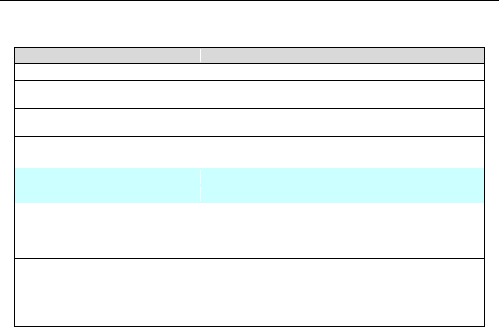
6
4. Specifications
4-1 Basic specifications
RX-8
Board transfer reference
Front reference only
Supported languages
Japanese, English and Chinese (simplified Chinese and traditional
Chinese) are switched in real time.
Board transfer height
900mm (-10/+30) mm
950mm (-20/+15) mm
Component height
P20 nozzle head: 3 mm
Head specification
Left
Right
P20 nozzle head P20 nozzle head
Component recognition system COM camera (reflected illumination)
Component size P20 nozzle head: 0402 to □ 5 mm
Placement
precision
P20 ±40 μm *Note 1
Number of component that can be placed
with the machine
Up to 56 component types (When an RF08AS is used)
EN specification
Supported
*Note 1: Only a 0603R shall conform to the regulation: CPK≧1 or more.
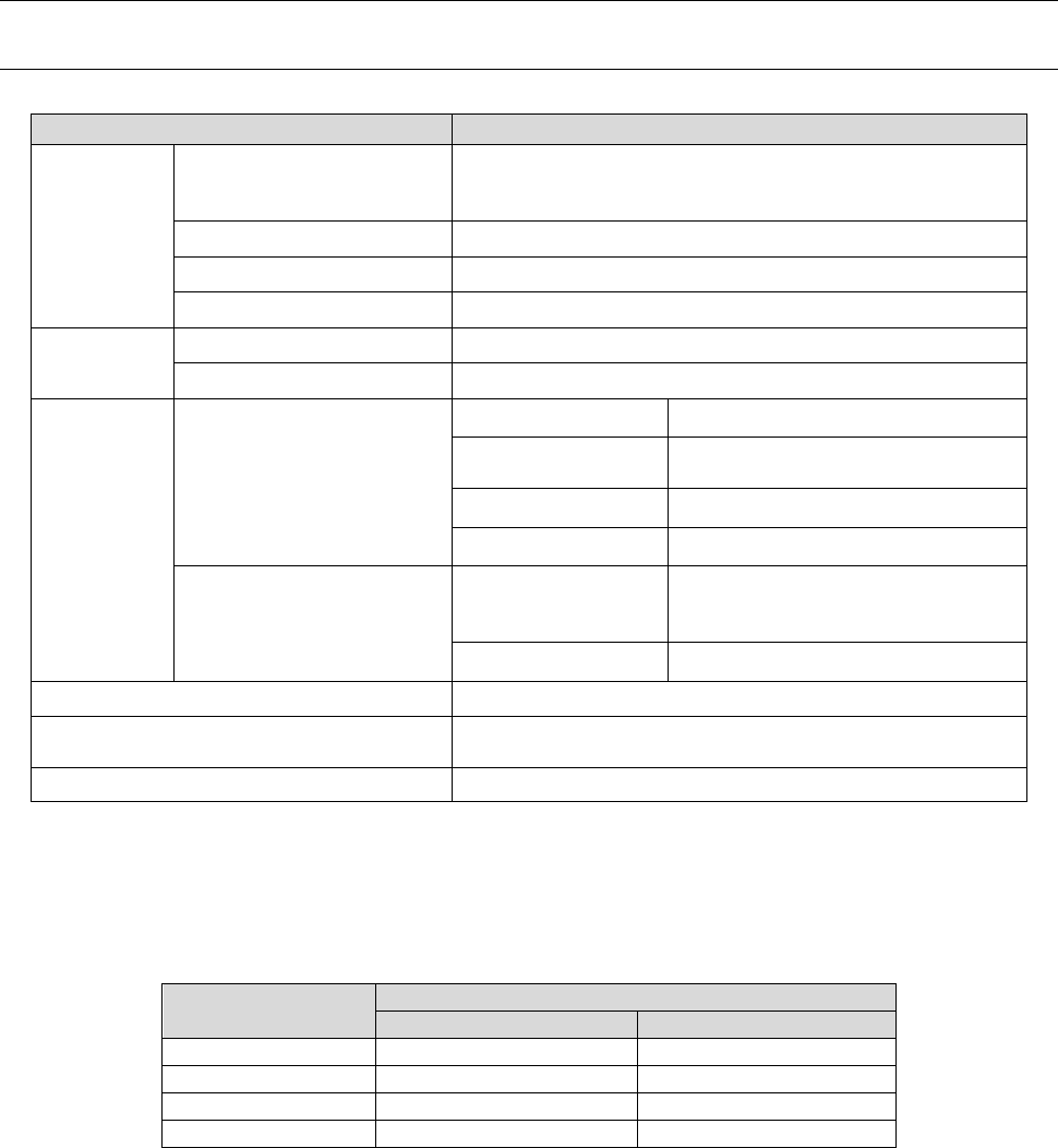
7
4-2 Facility specifications
4-2-1 Electrical specifications and environmental conditions
Supply
voltage
Voltage
3-phase 200 V AC (for a standard model)
Transformer option
3-phase 220V / 240V / 380V / 400V / 415V AC *Note 1
Frequency 50/60 Hz
Rated apparent power 2.1 kVA
Peak current (200 V AC) 42.3 A
Supply air
Air pressure 0.49 ± 0.05 Mpa Dry air
Maximum air consumption 20 L/minute (standard condition) *Note 2
Environmen
tal condition
When operating
Temperature + 10 to + 35ºC
Precision ensuring
temperature
+ 20 to + 25ºC
Humidity 30 to 70 %RH (No condensation)
Altitude 1,000 m or less
When transportation or
storage
Temperature
– 20 to + 65ºC
(Up to + 70ºC for a short time that
is 24 hours or less)
Humidity 30 to 80 %RH (No condensation)
Noise
73 dB (A) or less *Note 3
Degree of pollution
2 (Conforming to IEC60664-1, equivalent to the pollution
level of a general electric circuit board production line)
Overvoltage category III (Conforming to IEC60664-1) *Note 4
*Note 1: Any power cable is not supplied with the machine.
Since we cannot guarantee the user for any accident on wiring of the primary side caused by
a short circuit of the power cable or for any other reason, it is your sole responsibility to select
a breaker or a power cable. Note that you should use a power cable whose phase is 5.5
mm2 or more respectively. (Note that the applicable cross-sectional area of the power cable
varies depending on the supplied power voltage and the length of the cable.)
Cable length (m)
Sectional area of the electric conductor (mm
2
)
200-V system
400-V system
Less than 20
5.5
5.5
30
8.0
5.5
40
10.0
6.0
50
14.0
6.0
*Note 2: “Standard condition” indicates the following air condition: temperature 20ºC, absolute
pressure 0.1 MPa (= 100 k Pa = 1 bar), relative humidity 65 %.
The required supply air shall be calculated as follows:
In case of 20 L/minute (standard condition): 20/0.926 (coefficient) = 21.6 L/minute or more
air is required.
*Note 3: The noise shall be measured under the following conditions:
•
1.5 m above the floor far away from the front of the machine by 1 m
• The front cover of the machine shall be closed while the machine is operating as assumed
normally.
*Note 4: Applicable when a transformer option is attached on the machine (Overvoltage category II is
applied when any transformer option is not attached on the machine).