RX-8_SPE_EN.pdf - 第12页
8 4-2-2 External dimension drawing Dimension Single - lane conveyor specifications A (Length of the co nveyor) 998 mm C (excluding the LCD) 1, 893 mm H ( T rans port output amount) 8 mm I (From the front of the cover to …
7
4-2 Facility specifications
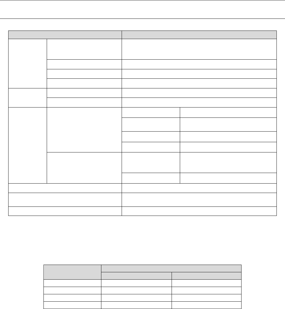
4-2-1 Electrical specifications and environmental conditions
Supply
voltage
Voltage
3-phase 200 V AC (for a standard model)
Transformer option
3-phase 220V / 240V / 380V / 400V / 415V AC *Note 1
Frequency 50/60 Hz
Rated apparent power 2.1 kVA
Peak current (200 V AC) 42.3 A
Supply air
Air pressure 0.49 ± 0.05 Mpa Dry air
Maximum air consumption 20 L/minute (standard condition) *Note 2
Environmen
tal condition
When operating
Temperature + 10 to + 35ºC
Precision ensuring
temperature
+ 20 to + 25ºC
Humidity 30 to 70 %RH (No condensation)
Altitude 1,000 m or less
When transportation or
storage
Temperature
– 20 to + 65ºC
(Up to + 70ºC for a short time that
is 24 hours or less)
Humidity 30 to 80 %RH (No condensation)
Noise
73 dB (A) or less *Note 3
Degree of pollution
2 (Conforming to IEC60664-1, equivalent to the pollution
level of a general electric circuit board production line)
Overvoltage category III (Conforming to IEC60664-1) *Note 4
*Note 1: Any power cable is not supplied with the machine.
Since we cannot guarantee the user for any accident on wiring of the primary side caused by
a short circuit of the power cable or for any other reason, it is your sole responsibility to select
a breaker or a power cable. Note that you should use a power cable whose phase is 5.5
mm2 or more respectively. (Note that the applicable cross-sectional area of the power cable
varies depending on the supplied power voltage and the length of the cable.)
Cable length (m)
Sectional area of the electric conductor (mm
2
)
200-V system
400-V system
Less than 20
5.5
5.5
30
8.0
5.5
40
10.0
6.0
50
14.0
6.0
*Note 2: “Standard condition” indicates the following air condition: temperature 20ºC, absolute
pressure 0.1 MPa (= 100 k Pa = 1 bar), relative humidity 65 %.
The required supply air shall be calculated as follows:
In case of 20 L/minute (standard condition): 20/0.926 (coefficient) = 21.6 L/minute or more
air is required.
*Note 3: The noise shall be measured under the following conditions:
•
1.5 m above the floor far away from the front of the machine by 1 m
• The front cover of the machine shall be closed while the machine is operating as assumed
normally.
*Note 4: Applicable when a transformer option is attached on the machine (Overvoltage category II is
applied when any transformer option is not attached on the machine).
8
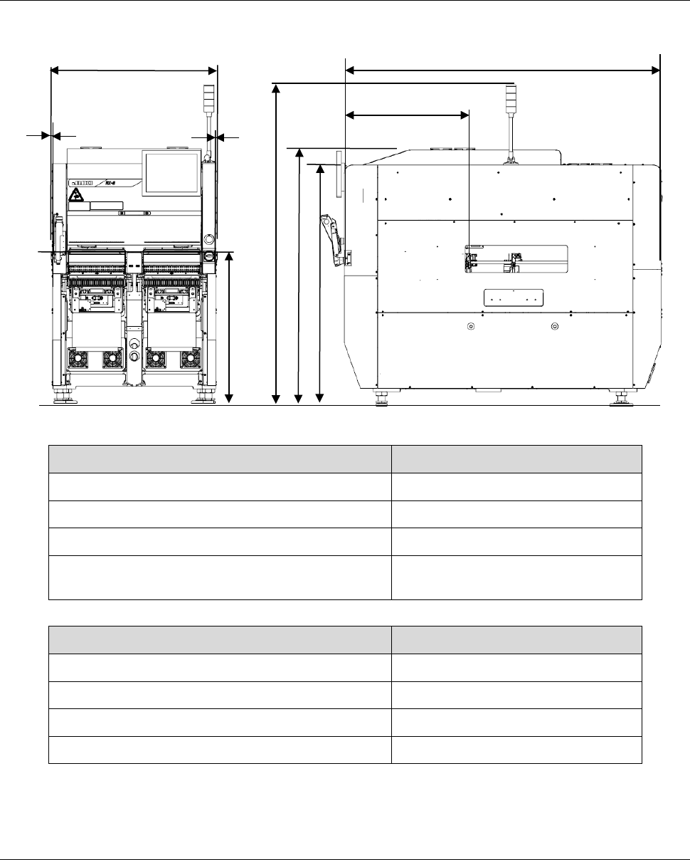
4-2-2 External dimension drawing
Dimension Single-lane conveyor specifications
A (Length of the conveyor) 998 mm
C (excluding the LCD) 1,893 mm
H (Transport output amount) 8 mm
I (From the front of the cover to the board transport
path on the reference side)
750. 5 mm (Front side)
Dimension
B (From the floor to the topside of the conveyor belt) 900 mm
E (From the floor to the topside of the cover 1) 1,440 mm
F (From the floor to the topside of the cover 2) 1,530 mm
G (From the floor to the topside of the signal light) 1,916 mm
The dimensions above exclude the maximum protuberance.
*1 The tolerance of the dimensions above shall be ± 5 mm.
4-2-3 Mass of the main unit
1,810 kg * Excluding options
H
C
H
A
B
G
F
I
E
9
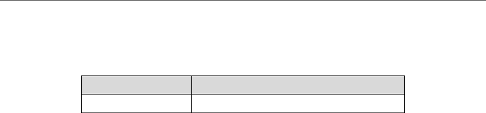
4-3 Component placement cycle time (Number of components to be
placed per hour)
P20 nozzle head
Component bottom recognition camera (equipped with a head)
Component side recognition camera (equipped with a head)
1 Unit: CPH
HEAD TYPE
Component placement cycle time *1
P20 nozzle head
55,000
*1 This is the number of components that can be placed for one hour when 400 pieces of 0603
capacitors are placed onto a 200 mm×200 mm board at each angle of 0, 90, 180 and 270
degrees sequentially. (This method conforms to IPC9850.)