RX-8_SPE_EN.pdf - 第25页
21 5. Standard F unctions an d Options 5-1 Standard functions 5-1-1 Bad mark detecting function By reading a bad mark (inferio r circuit) set on each circuit of a multi - circuit board, the machine ca n prevent any compo…
20
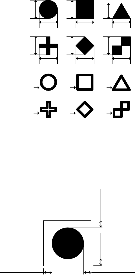
Shapes and dimensions of a recognition mark
A recognition mark shall conform to JIS C5010 “General rules for printed wiring boards” and
JPCA-PB01-2004 “Printed Wiring Boards.”
The standard marks represent 12 shapes as shown in the following figure, “Shapes of recognition
marks.”
Shapes of recognition marks
A
A
A
A
A
A
A
A
A
A
A
A
B
B
B
B
B
B
A: 0.4 mm or more but 2.0 mm or less
B: Width of 0.2 mm or more
The size of mark is limited.
Clearance of a recognition mark
There shall be a space in which any other marks such as a conductor pattern, a solder resist and a
marking are not located around each recognition mark. It is preferable that the dimensions of this
space are larger than those of a square by 0.5 mm or more viewed from the outside of a recognition
mark.
Clearance of a recognition mark
0.5 mm or more
0.5 mm or more
0.5mm or more 0.5 mm or more
21
5. Standard Functions and Options
5-1 Standard functions
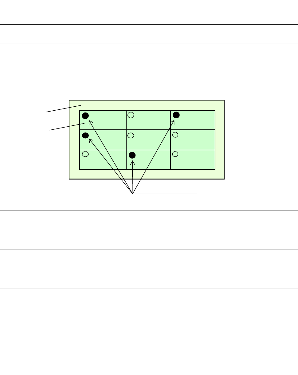
5-1-1 Bad mark detecting function
By reading a bad mark (inferior circuit) set on each circuit of a multi-circuit board, the machine can
prevent any component from being placed on the circuit.
The minimum diameter of a bad mark shall be 2.5 mm and the color of a mark should be highly
contrasted with that of a board.
The brightness of the board color can be switched when the reflected light quantity of the board color is
different from that of the mark.
5-1-2 Height measurement system (HMS)
The height measurement system measures the topside of a component or that of a paper tape to correct
the component pick-up height automatically.
5-1-3 Vacuum pump
This pump allows the machine to reduce air consumption of the compressor, and improve the stability of
air supply when it picks up a component.
5-1-4 Automatic board width adjustment function (AWC)
This is the function for adjusting the distance between the rails according to the width of a board
automatically.
5-1-5 Feeder float sensor
This function is provided to prevent mechanical troubles from being caused by improper installation of a
tape feeder. When this sensor detects an improperly-installed feeder, it stops the X-Y axes from moving,
and warns an operator.
5-1-6 Flexible calibration system (FCS)
After a component that is recognized with a camera is placed on a glass jig board, the FCS uses a
camera to automatically measure the difference between a value set with the program and the position at
which the component is placed actually, and calculates the offset value to be used for placing the
component.
A series of operations can be automatically performed when you set the jig board and load the program
to the machine.
Board
Circuit
Bad marks
22
When you use the FCS, you can check whether the precision is maintained and adjust the precision at
relocation or routine maintenance of the machine. *The calibration jig is optional.
5-1-7 White list type anti-virus software
This software prevents software such as virus software from invading the system after shipment of the
machine.
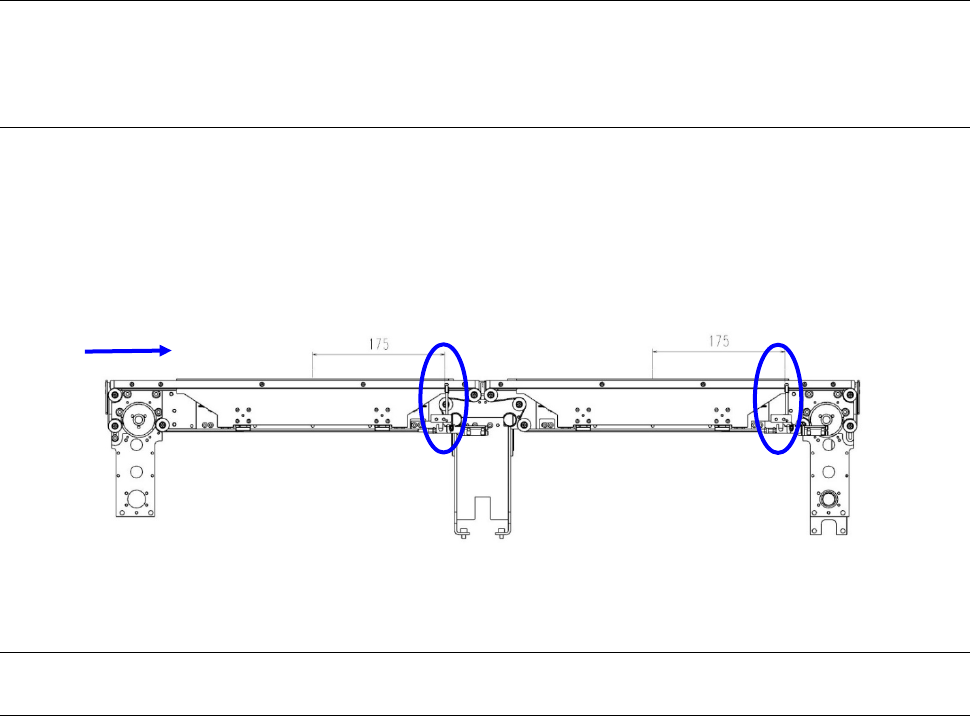
5-1-8 Board Stopper
• Location of the board stopper
The position of the board stopper is fixed at a position 175 mm from the center of the unit in the X
direction toward the board transfer direction. Its position is fixed in the Y direction also.
5-2 Option
5-2-1
Trolley for an electric feeder (equipped with an auto tape cutter and a trash box)
This trolley allows a group of feeders to be attached or detached onto/from the main unit at a time.
Since this option enables changeover from the current feeders to the next feeders even during
production of PWBs, it shortens the time required for changeover.
Conveyor direction