RX-8_SPE_EN.pdf - 第21页
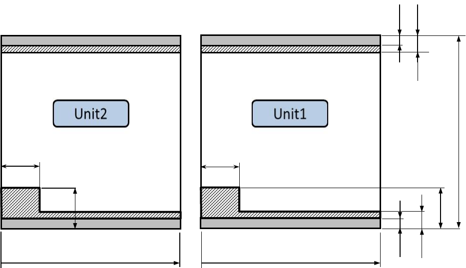
17 Single transfer spe cification devi c e (flow direction R to L) 50 ~ 450mm 40mm 40mm 3mm 3mm 8mm 8mm 40mm 50 ~ 350mm 50 ~ 350mm 40mm
16
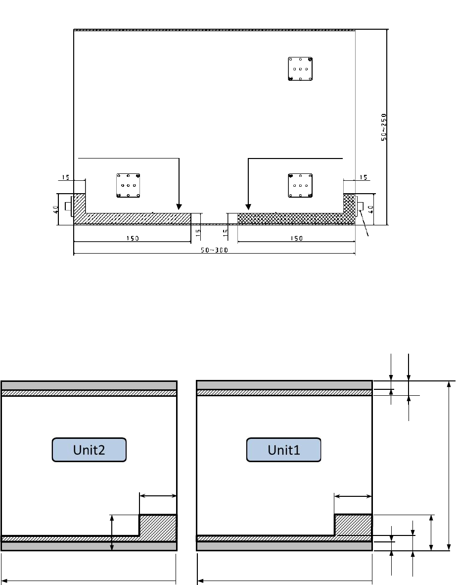
Area on which any back-up pin cannot be set when an RX-8 is used
RX-8: Area in which any back-up pin cannot be set
Single transfer specification device (flow direction L to R)
シ ン グ ル 仕様:
50
~
450mm
40m
40m
3mm
3mm
8mm
8mm
40m
40m
50
~
350mm
50
~
350mm
Area in which any pin cannot
be set when a board is
transferred from right to left
Area in which any pin cannot
be set when a board is
transferred from left to right
Stopper (Board transfer
direction: left to right)
Front of the machine
Unit: mm
Single specification: 50 to 450 mm
17
Single transfer specification device (flow direction R to L)
50
~
450mm
40mm
40mm
3mm
3mm
8mm
8mm
40mm
50
~
350mm
50
~
350mm
40mm
18
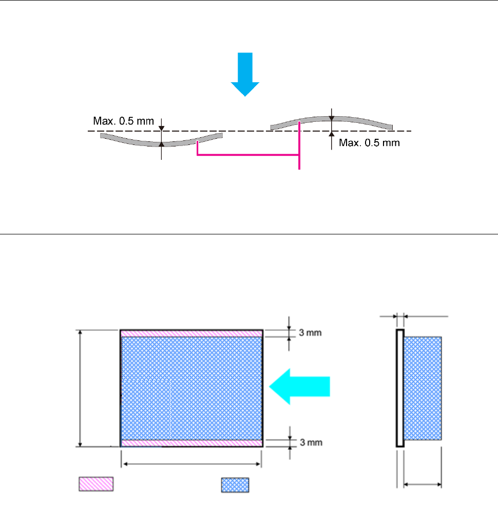
4-7-3 Allowable warpage of a board
4-7-4 Available area for placing a component on the topside and rear side of a board
As shown in the figure below, the machine cannot place any component in the area 3 mm from each
edge of a printed wiring board.
The maximum height of a component mounted on the rear side is 26 mm.
Component placement direction
Board
Flow
direction
Conveyor rail
section
Component installation
range that permits use of
the device
Board D
Board T
Board W
Bottom
side
26 mm