RX-8_SPE_EN.pdf - 第9页
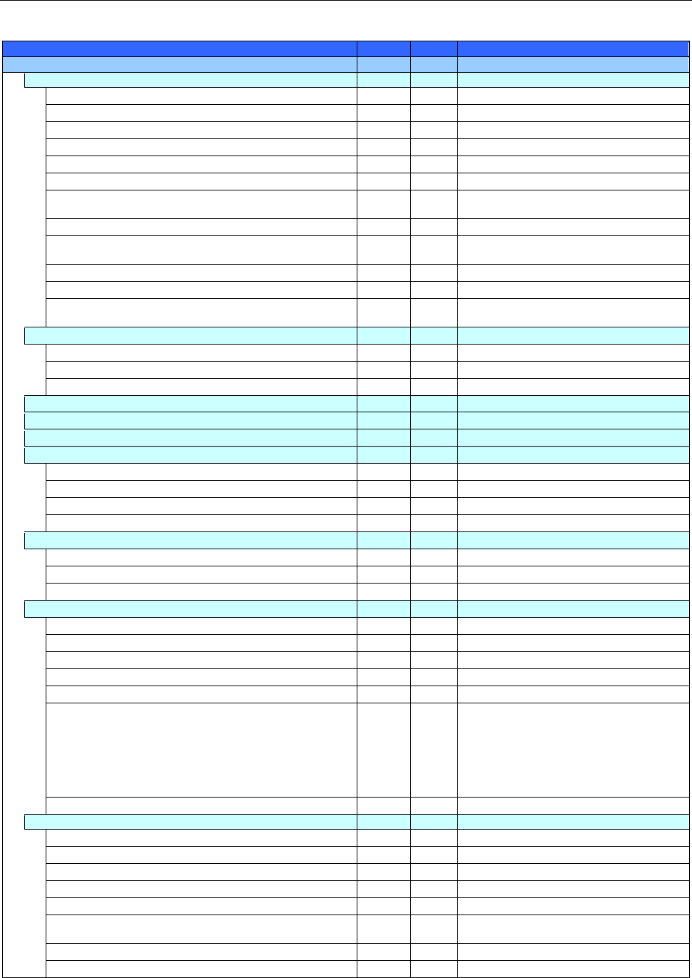
5 Equipment Feeder float sensor ○ ○ Automatic T ool Change unit (A TC) ○ ○ Large-sized component trash box - - Flexible Calibration System (FCS) ○ ○ FCS adjustment jig ● ● SOT direction inspection table - - Component V e…
4
3. System Configuration
○:Equipped as standard ●:Option -:No setting
Model name
RX-8
RX-7R
Remarks
Basic configuration
Attached heads
P16S nozzle head
- ○
P8 nozzle head
- ○
P20 nozzle head
○ -
Offset correction camera left (OCC-L)
○ ○
Offset correction camera right (OCC-R)
○ ○
Laser recognition unit
- -
Component bottom side recognition camera
(equipped with a head)
○ ○
P20/P16S nozzle head only
Component side recognition camera (equipped with a head)
○ ○
P20/P16S nozzle head only
Component bottom side recognition camera
(To be attached on the main unit)
- ○
RX-7R/P8 nozzle head only
Height Measurement System (HMS)
○ ○
Lighting unit for Solder recognition
- -
Bad mark reader
○ ○
This is the function for recognizing a mark
with the OCC.
Power supply unit
Emergency stop button
○ ○
ATX power supply unit (equipped with the UPS function)
○ ○
Electric leakage breaker
● ●
I/O control unit
Motor control unit
X-Y control unit
Interior/exterior finish and equipment
Signal light (equipped with a buzzer)
○ ○
Mini signal light
- -
Adjuster Rubber Sheet
- -
Caster
- -
Pneumatic device piping system
Air regulator
○ ○
Vacuum pump
○ ○
Main line filter
- -
PWB transport unit
Placement station
○ ○
Dual-lane conveyor
- ○
Front reference only
Auto PWB width adjustment unit
○ ○
Conveyor extension
- -
Board stopper
○ ○
L
board supported (board length 350mm or more up to
420mm)
○ ○
* Right and left heads can be mounted at
the same time. However, there are two
restrictions; (1) BOC mark out of mounting
range cannot be recognized, (2) For the
transfer operation for L board, the
mechanical stopper of unit on downstream
side cannot be used
Longer-sized board (PWB length 510mm or less)
○ ○
Operation system
Liquid Crystal Display
○ ○
Keyboard with a trackball
- -
SSD
○ ●
HDD
- ○
LAN port Ethernet
○ ○
USB port (Front×2)
○ ○
We don't guarantee the function to all of
USB memories.
Rear-side operation unit
- -
DVD/CD-ROM drive (USB)
- -
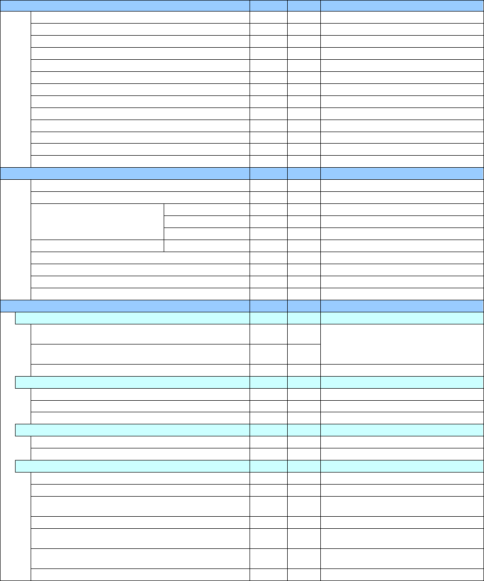
5
Equipment
Feeder float sensor
○ ○
Automatic Tool Change unit (ATC)
○ ○
Large-sized component trash box
- -
Flexible Calibration System (FCS)
○ ○
FCS adjustment jig
● ●
SOT direction inspection table
- -
Component Verification System (CVS)
- ●
P16S nozzle head only
Coplanarity
- -
Fluxer: Type 2 (To be attached on the main unit)
- -
Low load control
- -
High-load control
- -
Offset Placement After Solder Screen-printing
- ●
ADVANCE KIT
- ●
P16S head only / Retrofit only
Production support system
White list type anti-virus software
○ ○
Floor productivity improvement support system
Production support system
IS Lite
- -
IS
- -
JaNets
● ●
After Ver2.05 (RX-7R)
Production control system
IFS-NX
● ●
After Ver1.90 (RX-7R)
Flexline CAD
- -
Component Database for a main unit
● ●
After Ver2.10 (RX-7R)
Component Database for a server
● ●
After Ver2.10 (RX-7R)
External Programming Unit (EPU)
- -
Component supply device
Feeder bank for supporting an electric tape feeder
Designed for a feeder exchange trolley EF
(Equipped with a tape cutter and a trash box)
- ●
Front left and right
You have to select a trolley type.
Designed for a feeder exchange trolley RF
(Equipped with a tape cutter and a trash box)
● ●
Fixed type
● ●
RF only
Component supply unit
Electric tape feeder EF series
- ●
Electric tape feeder RF series
● ●
Stick feeder
- -
Tray supply unit
MTC/MTS
- -
Tray holder
- -
Other supplied devices
Tape reel mounting base for an electric feeder (EF)
- ●
Tape reel mounting base for an electric feeder (RF)
● ●
RF_ETFR ATTACHMENT - ●
Attach this component when electric
feeders are used by a feeder trolley (RF).
IC collection belt
- -
Fluxer: Type 3
(To be attached on a bank/rear side only)
- -
Rotary-type solder transfer device
(To be attached on a bank/front side only)
- -
Power supply for setting up an electric bank
- -
6
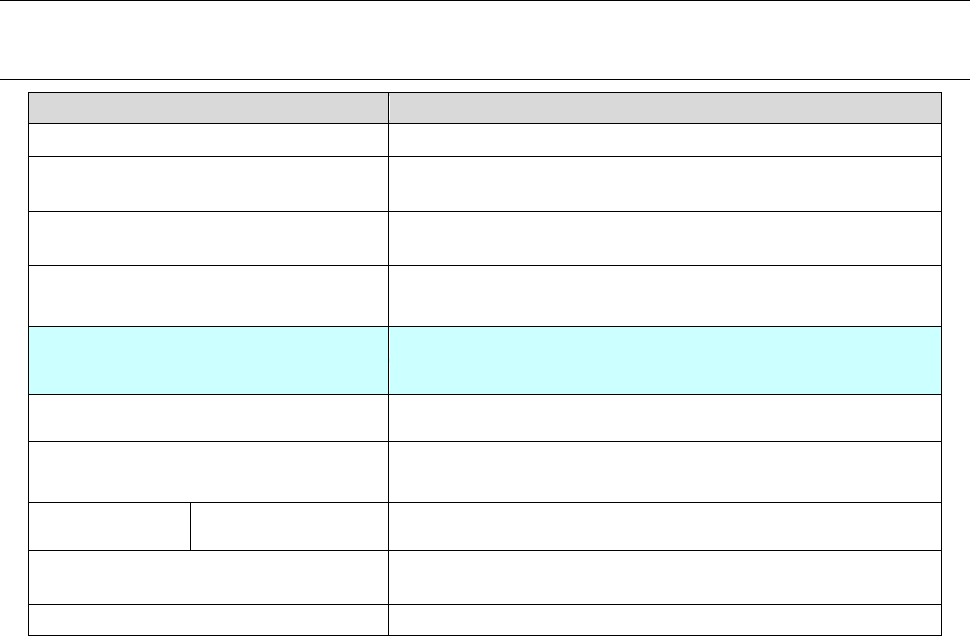
4. Specifications
4-1 Basic specifications
RX-8
Board transfer reference
Front reference only
Supported languages
Japanese, English and Chinese (simplified Chinese and traditional
Chinese) are switched in real time.
Board transfer height
900mm (-10/+30) mm
950mm (-20/+15) mm
Component height
P20 nozzle head: 3 mm
Head specification
Left
Right
P20 nozzle head P20 nozzle head
Component recognition system COM camera (reflected illumination)
Component size P20 nozzle head: 0402 to □ 5 mm
Placement
precision
P20 ±40 μm *Note 1
Number of component that can be placed
with the machine
Up to 56 component types (When an RF08AS is used)
EN specification
Supported
*Note 1: Only a 0603R shall conform to the regulation: CPK≧1 or more.