RX-8_SPE_EN.pdf - 第18页
14 4-7 Specifications of applicab le boards 4-7-1 Board transport direction Rightward flow (trans porting from left to right viewed from the f ront side) Leftward flow (tran s porting from right to left viewed fro m the …
13
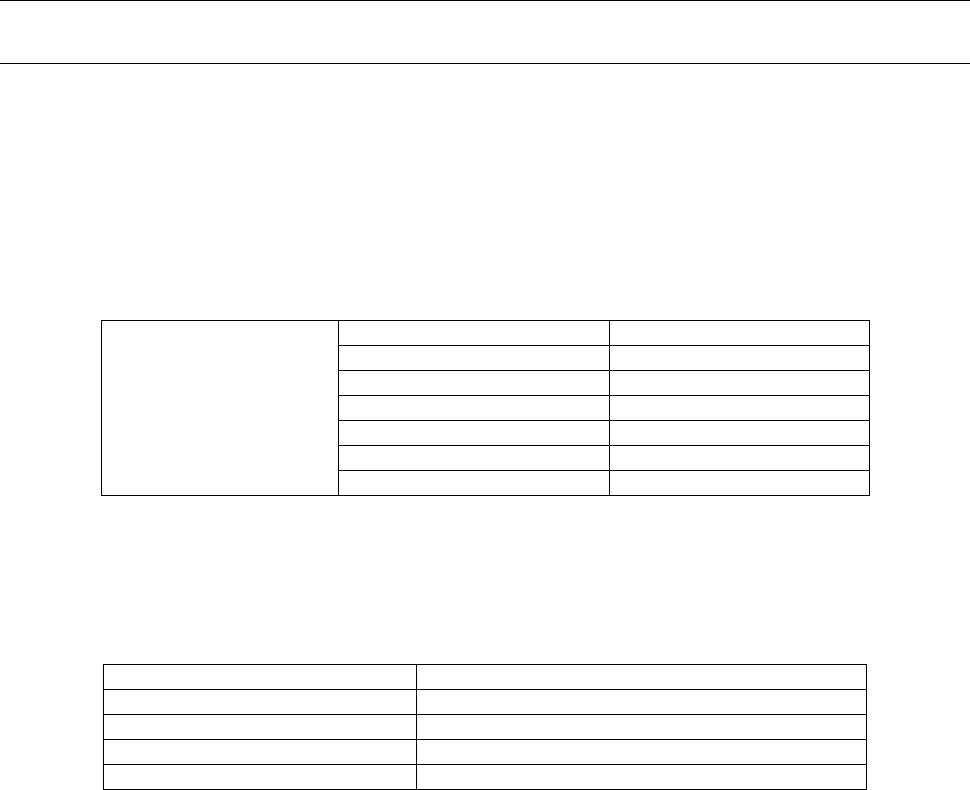
4-6 Component placement accuracy
4-6-1 P20 nozzle head
• The component placement accuracy is determined with considering 20 nozzles in total and that of
each axis is not regulated.
• If you change the setup of the machine, this accuracy shall be applied to the second use of nozzles
(that is, the 21
st
and subsequent component placements) after all nozzles finish placing components
once.
• The ball diameter of BGA, 0.25 mm and, the pitch are 0.4 mm or more.
(1) Component placement position
(Unit: μm)
P20 nozzle head
(20 nozzle)
Square chip 0402R/0402C
±40
Square chip 0603R
±40
Square chip 0603C
±40
Square chip 1005R/1005C
±40
Square chip 1608
(for reference) ± 80
Square chip 2012 or larger
(for reference) ±100
Edge light LED
(for reference) ±150
CPK ≧ 1 or more shall be applied to a 0603R only.
(2) Component placement attitude accuracy
P20 head placement attitude accuracy (Unit: º)
Square chip 0402R/0402C
±3
Square chip 0603R/0603C
±3
Square chip 1005R/1005C
±3
Square chip 1608 or larger
(for reference) ±2.5
Edge light LED
(for reference) ±2.5
CPK ≧ 1 or more is not regulated.
14
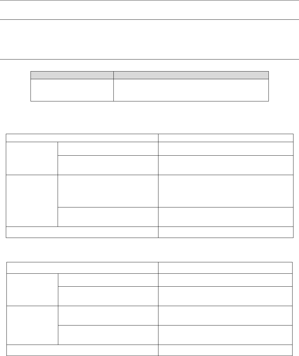
4-7 Specifications of applicable boards
4-7-1 Board transport direction
Rightward flow (transporting from left to right viewed from the front side)
Leftward flow (transporting from right to left viewed from the front side)
4-7-2 Board dimensions and mass
Item
Specification
Transport weight
2.0 kg or less
*Contact us if the weight exceeds the upper limit.
When a board is transferred with a single lane (in Normal PWB mode)
Item
Specification
Dimensions of an
applicable board
When not equipped with a board
stopper
Min.: 50 mm x 50 mm
Max.: 42
0
mm x 450 mm
When equipped with a board stopper
(3) (The stopper is located at a “175
mm” position.)
Min.: 50 mm x 50 mm
Max.: 420 mm x 450 mm
Area of a board in
which a
component can
be placed
When not equipped with a board
stopper
X direction: A component can be placed in the
area ± 175 mm viewed from the center of the unit
according to the board stop position.
Y direction: 3 mm to (“Board width” – 3) mm on the
board front side
When equipped with a board stopper
(3) (The stopper is located at a “175
mm” position.)
X direction: No limitations
Y direction: 3 mm to (“Board width” – 3) mm on the
board front side
Board thickness 0.3 mm to 6.0 mm
When a board is transferred with a single lane (in Long PWB mode)
Item
Specification
Dimensions of an
applicable board
When not equipped with a board
stopper
Min.: 50 mm x 50 mm
Max.: 510 mm x 450 mm
When equipped with a board stopper
(3) (The stopper is located at a “175
mm” position.)
Min.: 50 mm x 50 mm
Max.: 510 mm x 450 mm
Area of a board in
which a
component can
be placed
When not equipped with a board
stopper
X direction: No limitations
Y direction: 3 mm to (“Board width” – 3) mm on the
board front side
When equipped with a board stopper
(3) (The stopper is located at a “175
mm” position.)
X direction: No limitations
Y direction: 3 mm to (“Board width” – 3) mm on the
board front side
Board thickness 0.3 mm to 6.0 mm

15
Note
•
If the board size X exceeds 350mm in usual PWB mode, only the unit on upstream side
against the board transfer direction manufactures the products using the stopper even if the
board stopper 3 is specified.
•
If the board size X exceeds 350mm in usual PWB mode, BOC/area mark and bad mark
linked to mounting step (or circuit) need to exist within the mounting range of unit which
mounts parts.
•
If the board size X exceeds 350mm in usual PWB mode, the global bad mark needs to exist
within the mounting range of upstream unit.
•
In Long PWB mode, only a unit on the downstream side viewed from the board transfer
direction uses a board stopper to produce a PWB.
•
In case of long PWB mode, BOC/area mark linked to mounting step (or circuit) needs to
exist within the mounting range of unit which mounts parts.
•
In case of long PWB mode, the bad mark linked to mounting step (or circuit) needs to exist
within the mounting range of unit which mounts parts or within the mounting range of
upstream unit.
•
In case of long PWB mode, the global bad mark needs to exist within the mounting range of
upstream unit.