RX-8_SPE_EN.pdf - 第33页
29 8. Interface 8-1 Electric interface 8-1-1 Kinds and meanings of electr ical signals The conceptual diag r am of the electrical sig nals sent/received to/from both the RX -8 and an upstream/down s tream device is sho w…
28
7. Control System
7-1 Control
7-1-1 Saving a program
This machine saves a production program onto the SSD in the main unit.
When you use a USB port, you can store it on an external storage device also.
7-1-2 Production program capacity
Maximum number of circuits per board: 1,200 for a matrix board
Maximum number of placement positions per board: 10,000 positions
Maximum number of component data records: maximum number of component types that
can be placed on the machine
Maximum number of pick data records: same as the above.
Maximum number of marks that can be registered to the machine: 1,250 sets of BOC marks
7-2 Operation mode
The following three operation modes are available during PWB production.
• Normal
The machine produces PWBs in Normal mode.
• Trial
The machine produces PWBs in Trial mode.
• Pass-through
The machine transports boards from an upstream device to a downstream device only without
placing any component on a board.
29
8. Interface
8-1 Electric interface
8-1-1 Kinds and meanings of electrical signals
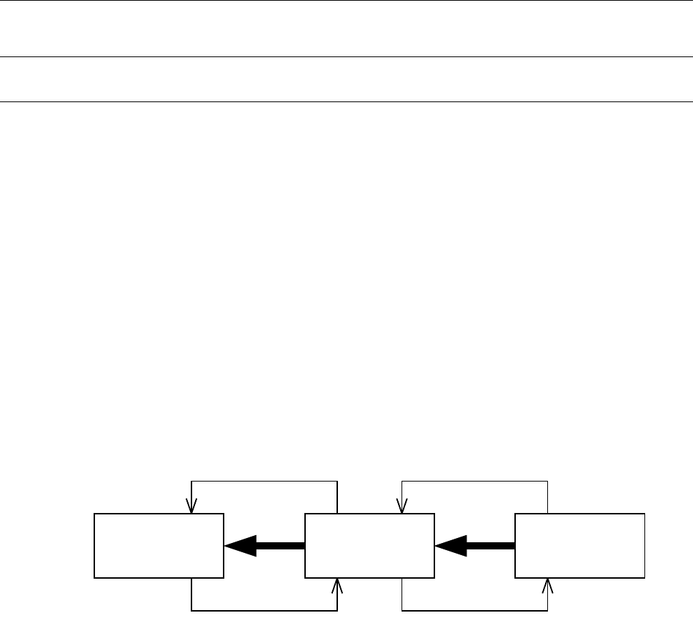
The conceptual diagram of the electrical signals sent/received to/from both the RX-8 and an
upstream/downstream device is shown in the figure “Conceptual diagram of electrical signal connection”
below.
The electrical signals transmitted between the RX-8 and an upstream-side device, ① and ②, and those
between the RX-8 and a downstream-side device, ③ and ④, are shown below.
a) The electrical signal ① is called a “board eject request input signal (or Board Available In)” and
receives a PWB eject request from an upstream device.
b) The electrical signal ② is called a “board eject permission output signal (or Ready Out)” and
causes a PWB to be ejected to an upstream device.
c) The electrical signal ③ is called a “board eject request output signal (or Board Available Out)” and
requests a downstream device to eject a PWB.
d) The electrical signal ④ is called a “board eject permission input signal (or Ready In)” and receives
PWB eject permission from a downstream device.
Conceptual diagram of electrical signal connection
下流側装置
③
①
②
④
マウンター
上流側装置
Downstream
device
RX-8
Upstream
device
30
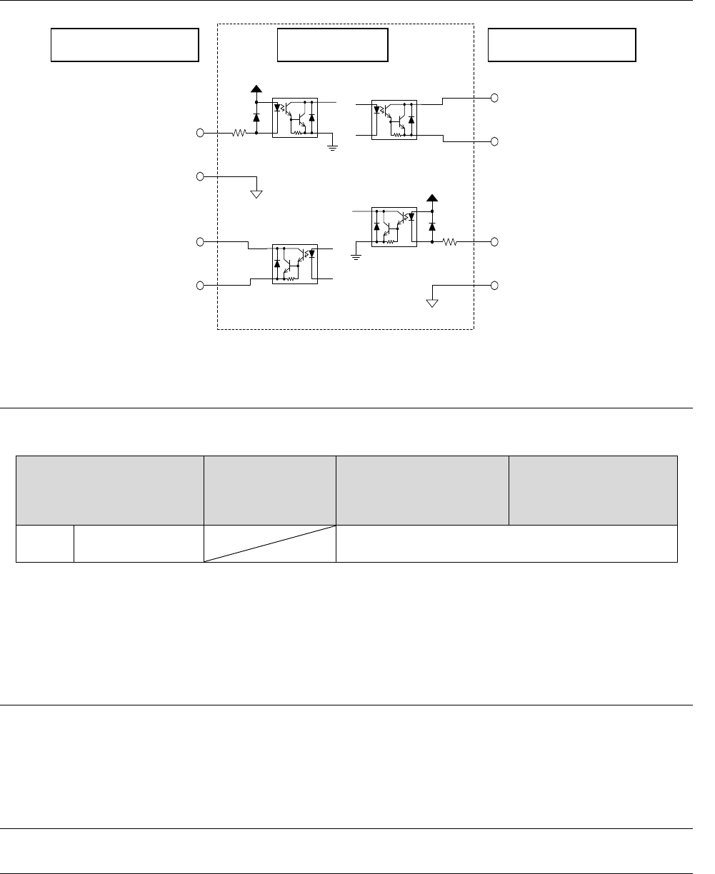
8-2 Input and output signal interface
24V
搬出要求入力信号
ピン
番号
:
1(
フロント側)
ピン番号:9(リア側)
搬出要求信号コモン
ピン番号:2(
フロント側)
ピン番号:10
(リア
側
)
下流側装置
搬出許可出力信号
ピン
番号:
3
(フロント
側
)
ピン番号:11(
リア
側)
搬出許可信号
コモン
ピン
番号:4(フロント
側)
ピン番号:12(リア側)
24V
搬出許可入力信号
ピン番号:3(フロント側
)
ピン
番号:11(リア側)
搬出許可信号
コモン
ピン番号
:4(フロント側)
ピン
番号:12(リア側)
搬出要求出力信号
ピン番号:1(フロント側)
ピン番号
:9(リア側)
搬出要求信号コモン
ピン番号:2(フロント側)
ピン
番号
:
10(
リア
側)
マウンタ
上流側装置
Figure Signal interface and connected terminals
8-2-1 Specifications of a connection cable
Use one of the following connection cables according to a machine you use.
Table of cables to be used
RX-7/ RX-7R /
RX-6
(Dual Mode)
RX-7 / RX-7R / RX-6,
KE-3020VA
(Single mode / Lane
device)
Inspection machine and
another device
(Dual-Lane device)
RX-8 Single mode 0, 1, 2
0: Joint cable (conventional cable : E9599705*A0)
1: Joint cable 1 (Standard attached to RX-7 / RX-7R options : EZ184657712)
2: Joint cable 2 (optional : EZ184660811)
8-3 Data interface
A LAN (10/100/1000BASE-T) is provided as the JaNets interface.
You can use a CD-ROM to be connected via the USB as the interface of the main unit.
(Two USB connecters are located on the front side.)
8-4 Utility connection
8-4-1 Piping joint
A Nittoh Kohki Hi Cupla (20PM) is located on the air supply port of the main unit.
A one-touch coupler is supplied with the machine at the factory.
• Nittoh Kohki Co., Ltd. Hi Cupla Model: 20SH
Downstream device Mounter Upstream device
Board eject request input signal
Pin number: 1 (front side)
Pin number: 9 (rear side)
Board eject request signal
common
Pin number: 2 (front side)
Pin number: 10 (rear side)
Board eject permission
output signal
Pin number: 3 (front side)
Pin number: 11 (rear side)
Board eject permission
signal common
Pin number: 4 (front side)
Pin number: 12 (rear side)
Board eject request output signal
Pin number: 1 (front side)
Pin number: 9 (rear side)
Board eject request signal common
Pin number: 2 (front side)
Pin number: 10 (rear side)
Board eject permission input signal
Pin number: 3 (front side)
Pin number: 11 (rear side)
Board eject permission signal common
Pin number: 4 (front side)
Pin number: 12 (rear side)