RX-8_SPE_EN.pdf - 第20页
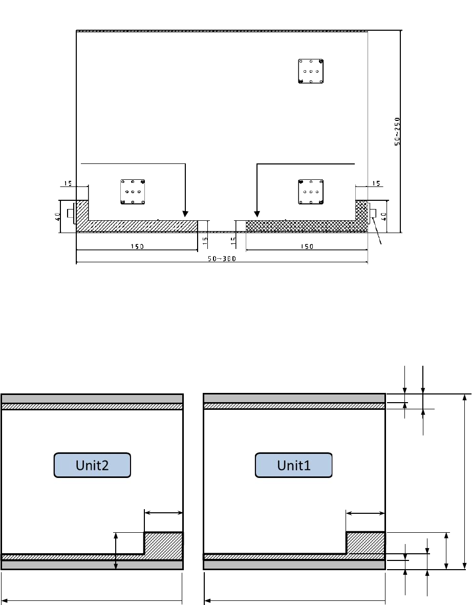
16 Area on which any b ack - up pin cannot be set wh en an RX - 8 is used RX -8 : Area in which an y back - up pin canno t be set Single transfer spe cification devi c e (flow direction L to R) シ ン グ ル 仕様: 50 ~ 450mm…

15
Note
•
If the board size X exceeds 350mm in usual PWB mode, only the unit on upstream side
against the board transfer direction manufactures the products using the stopper even if the
board stopper 3 is specified.
•
If the board size X exceeds 350mm in usual PWB mode, BOC/area mark and bad mark
linked to mounting step (or circuit) need to exist within the mounting range of unit which
mounts parts.
•
If the board size X exceeds 350mm in usual PWB mode, the global bad mark needs to exist
within the mounting range of upstream unit.
•
In Long PWB mode, only a unit on the downstream side viewed from the board transfer
direction uses a board stopper to produce a PWB.
•
In case of long PWB mode, BOC/area mark linked to mounting step (or circuit) needs to
exist within the mounting range of unit which mounts parts.
•
In case of long PWB mode, the bad mark linked to mounting step (or circuit) needs to exist
within the mounting range of unit which mounts parts or within the mounting range of
upstream unit.
•
In case of long PWB mode, the global bad mark needs to exist within the mounting range of
upstream unit.
16
Area on which any back-up pin cannot be set when an RX-8 is used
RX-8: Area in which any back-up pin cannot be set
Single transfer specification device (flow direction L to R)
シ ン グ ル 仕様:
50
~
450mm
40m
40m
3mm
3mm
8mm
8mm
40m
40m
50
~
350mm
50
~
350mm
Area in which any pin cannot
be set when a board is
transferred from right to left
Area in which any pin cannot
be set when a board is
transferred from left to right
Stopper (Board transfer
direction: left to right)
Front of the machine
Unit: mm
Single specification: 50 to 450 mm
17
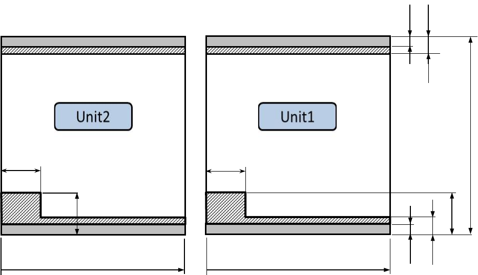
Single transfer specification device (flow direction R to L)
50
~
450mm
40mm
40mm
3mm
3mm
8mm
8mm
40mm
50
~
350mm
50
~
350mm
40mm