RX-8_SPE_EN.pdf - 第32页
28 7. Control Sys tem 7-1 Cont rol 7-1-1 Saving a program This machine saves a p roduction program onto the SS D in the mai n unit. When you use a USB port, you can store it on an external stor age device also. 7-1-2 Pro…

27
6-3-2 Tape reel mounting base
This is a mounting base for attaching a tape reel onto a tape feeder. Since it allows you to attach a tape
reel on a tape feeder while keeping the tape feeder in position, the tape attachment capability is
improved and it also functions to prevent a tape feeder from falling.
Specifications
1. RF-FSS
Feeder setup stand RF
Power supply
Input side: 90 to 250 V AC
Output side: DC 24V, DC5V
Frequency Input side: 50/60 Hz
Current
Input side: 1.4A / 0.7A (100V/200V) typical
Output side:3 A (maximum)
Outside dimensions
L=550mm
W=470mm
H=950±50mm
Mass
25kg (Equipped with a stand)
Number of feeders to which
power can be supplied
1
* The outside dimensions/mass described above indicated values to be applied when any feeder is
not mounted on the base.
6-3-3 Electric Trolley Power Station
Power supply for an electric feeder exchange trolley
This is an optional unit that supplies power to a feeder exchange trolley for an electric feeder in order to
set a tape onto an electric tape feeder (ETF type) without removing the feeder from the electric feeder
exchange trolley. This shall be used for an electric feeder exchange trolley only.
Model PW02
Power supply 100 – 120 V/200 – 240 V AC
Frequency 50/60 Hz
Rated power 600 VA
Output voltage DC 24 V ± 10 %
Output current 18.0 A (Max)
External dimensions (L/W/H) 308mm × 290mm × 540mm
Mass Approximately 16 kg
Connection feeder exchange
trolley number
2
Remarks
Equipped with a MPC-CAN.
It can communicate with the IFS-NX server by connecting
a LAN cable.
* When using Electric Trolley Power Station, Electric Trolley Power Station and TROLLEY POWER
CABLE ASM are needed.

28
7. Control System
7-1 Control
7-1-1 Saving a program
This machine saves a production program onto the SSD in the main unit.
When you use a USB port, you can store it on an external storage device also.
7-1-2 Production program capacity
Maximum number of circuits per board: 1,200 for a matrix board
Maximum number of placement positions per board: 10,000 positions
Maximum number of component data records: maximum number of component types that
can be placed on the machine
Maximum number of pick data records: same as the above.
Maximum number of marks that can be registered to the machine: 1,250 sets of BOC marks
7-2 Operation mode
The following three operation modes are available during PWB production.
• Normal
The machine produces PWBs in Normal mode.
• Trial
The machine produces PWBs in Trial mode.
• Pass-through
The machine transports boards from an upstream device to a downstream device only without
placing any component on a board.
29
8. Interface
8-1 Electric interface
8-1-1 Kinds and meanings of electrical signals
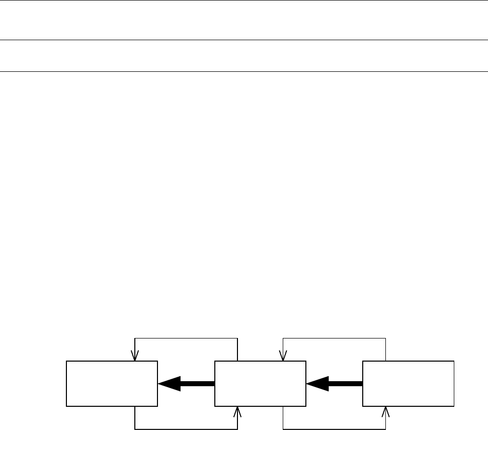
The conceptual diagram of the electrical signals sent/received to/from both the RX-8 and an
upstream/downstream device is shown in the figure “Conceptual diagram of electrical signal connection”
below.
The electrical signals transmitted between the RX-8 and an upstream-side device, ① and ②, and those
between the RX-8 and a downstream-side device, ③ and ④, are shown below.
a) The electrical signal ① is called a “board eject request input signal (or Board Available In)” and
receives a PWB eject request from an upstream device.
b) The electrical signal ② is called a “board eject permission output signal (or Ready Out)” and
causes a PWB to be ejected to an upstream device.
c) The electrical signal ③ is called a “board eject request output signal (or Board Available Out)” and
requests a downstream device to eject a PWB.
d) The electrical signal ④ is called a “board eject permission input signal (or Ready In)” and receives
PWB eject permission from a downstream device.
Conceptual diagram of electrical signal connection
下流側装置
③
①
②
④
マウンター
上流側装置
Downstream
device
RX-8
Upstream
device