RX-8_SPE_EN.pdf - 第35页
31 9. Safety Speci fications 9-1 Standard specifications Emergency stop The machine is equipped with one emergency stop butt on on the front side. Depressing the em ergency sto p button immediately stops each axis to cut…
30
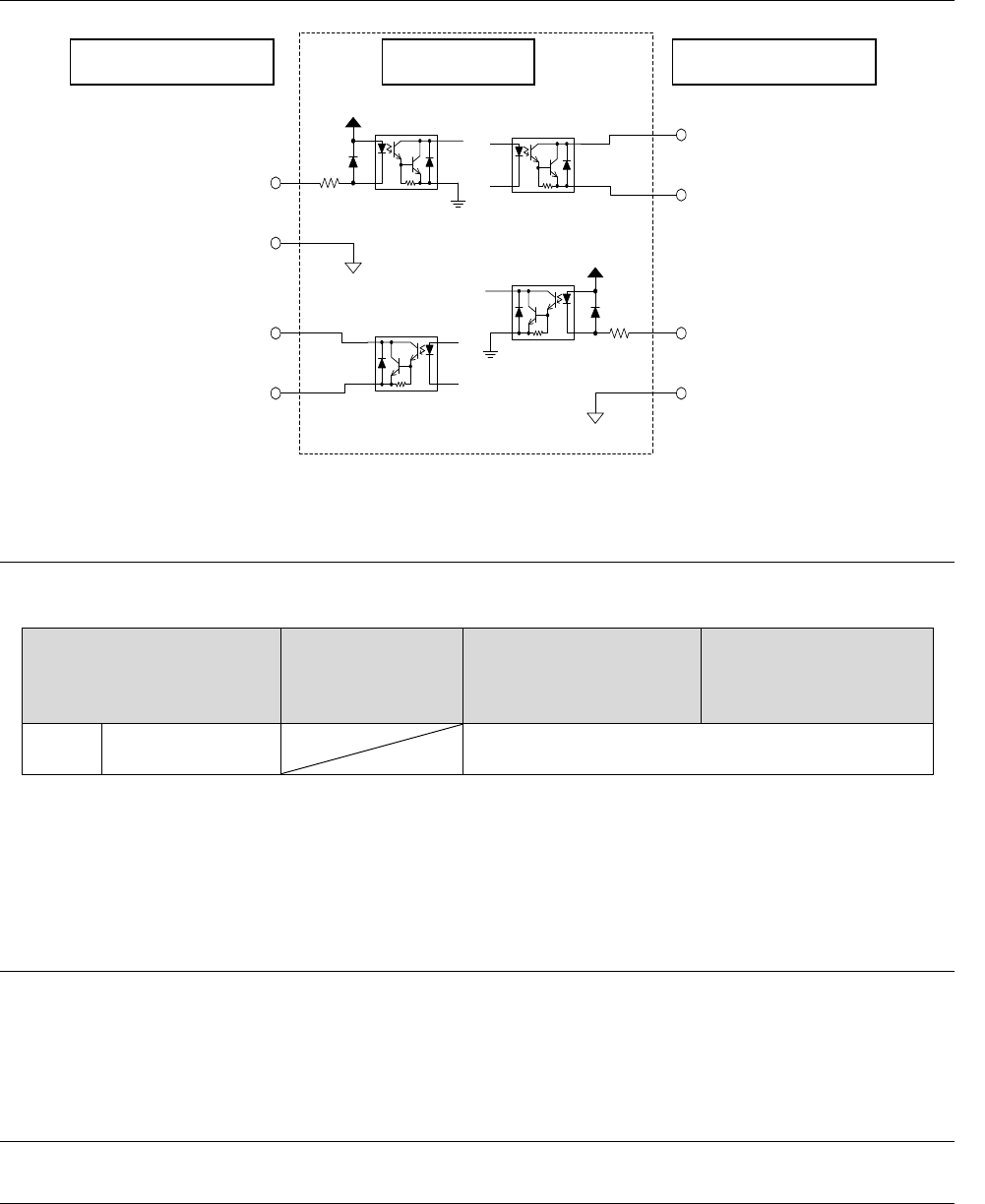
8-2 Input and output signal interface
24V
搬出要求入力信号
ピン
番号
:
1(
フロント側)
ピン番号:9(リア側)
搬出要求信号コモン
ピン番号:2(
フロント側)
ピン番号:10
(リア
側
)
下流側装置
搬出許可出力信号
ピン
番号:
3
(フロント
側
)
ピン番号:11(
リア
側)
搬出許可信号
コモン
ピン
番号:4(フロント
側)
ピン番号:12(リア側)
24V
搬出許可入力信号
ピン番号:3(フロント側
)
ピン
番号:11(リア側)
搬出許可信号
コモン
ピン番号
:4(フロント側)
ピン
番号:12(リア側)
搬出要求出力信号
ピン番号:1(フロント側)
ピン番号
:9(リア側)
搬出要求信号コモン
ピン番号:2(フロント側)
ピン
番号
:
10(
リア
側)
マウンタ
上流側装置
Figure Signal interface and connected terminals
8-2-1 Specifications of a connection cable
Use one of the following connection cables according to a machine you use.
Table of cables to be used
RX-7/ RX-7R /
RX-6
(Dual Mode)
RX-7 / RX-7R / RX-6,
KE-3020VA
(Single mode / Lane
device)
Inspection machine and
another device
(Dual-Lane device)
RX-8 Single mode 0, 1, 2
0: Joint cable (conventional cable : E9599705*A0)
1: Joint cable 1 (Standard attached to RX-7 / RX-7R options : EZ184657712)
2: Joint cable 2 (optional : EZ184660811)
8-3 Data interface
A LAN (10/100/1000BASE-T) is provided as the JaNets interface.
You can use a CD-ROM to be connected via the USB as the interface of the main unit.
(Two USB connecters are located on the front side.)
8-4 Utility connection
8-4-1 Piping joint
A Nittoh Kohki Hi Cupla (20PM) is located on the air supply port of the main unit.
A one-touch coupler is supplied with the machine at the factory.
• Nittoh Kohki Co., Ltd. Hi Cupla Model: 20SH
Downstream device Mounter Upstream device
Board eject request input signal
Pin number: 1 (front side)
Pin number: 9 (rear side)
Board eject request signal
common
Pin number: 2 (front side)
Pin number: 10 (rear side)
Board eject permission
output signal
Pin number: 3 (front side)
Pin number: 11 (rear side)
Board eject permission
signal common
Pin number: 4 (front side)
Pin number: 12 (rear side)
Board eject request output signal
Pin number: 1 (front side)
Pin number: 9 (rear side)
Board eject request signal common
Pin number: 2 (front side)
Pin number: 10 (rear side)
Board eject permission input signal
Pin number: 3 (front side)
Pin number: 11 (rear side)
Board eject permission signal common
Pin number: 4 (front side)
Pin number: 12 (rear side)

31
9. Safety Specifications
9-1 Standard specifications
Emergency stop
The machine is equipped with one emergency stop button on the front side.
Depressing the emergency stop button immediately stops each axis to cut off the power supply for
driving the servomotors.
Safety cover
The machine is equipped with a cover on the front side. The cover open switch detects the cover
opening or closing state. When you open the cover, it interrupts transmission of power to each axis,
and the machine is put into the emergency stop state.
Moreover, each feeder trolley is equipped with a safety switch, and when the trolley is moved down,
transmission of power to each axis is interrupted, and the machine is put into the emergency stop
state. (Any operation of the conveyor belt, the support table or the component supply device is not
affected with this emergency stop.)
Even though you press the Start switch while the cover is opened or while the trolley is moved down,
the machine displays the corresponding message without operating any axis.
Interlock specifications
While the cover opens or while a feeder trolley is moved down, the power system including the
XY-axes is turned off.
9-2 Specifications of the CE marking
The machine conforms to the following EC directives:
• EC machinery directive 2006/42/EC
• EC EMC directive 2014/30/EU
• EC RoHS directive 2011/65/EU
Applicable standards
Machinery directives EN IS012100:2010, EN60204-1:2006+Al:2009, EN ISO13849-1:2015
EMC directives EN61000-6-4:2007+A1:2011, EN IEC61000-6-2:2019,
EN61000-4-2:2009,
EN61000-4-3:2006+A1:2008+A2:2010, EN61000-4-4:2012,
EN61000-4-5:2014+A1:2017, EN61000-4-6:2014, EN61000-4-8:2010,
EN61000-4-34:2005+A1: 2009
EC RoHS directive EN IEC63000:2018
9-3 Other laws and regulations
Laser device
HMS: Class II (JIS C6802 Class 2, FDA Class II), EN60825

32
10. Reliability Specifications
10-1 Reliability of the main unit (devices)
Life of the machine: Five years (excluding either the consumable components or the following parts)
Periodic replacement parts: These must be replaced at intervals of 2 to 3 years as a guideline. (The
replacement interval varies depending on the operating conditions.)
• Veyor cable assembly
• Air tube
• Air filter
• Gas spring
• Battery unit
• Vacuum pump
• Solenoid valve
• Camera
• Sensor
• Air cylinder
• Tape cutter unit and cutter blade (one year)
• Cable for setting up an electric feeder
• Conveyor belt
• Fuse
• Head mechanical valve
Criteria for calculating the reliability : 22 hours per day
: 300 days per year
: 22 × 300 × 5 = 33,000 hours