JAKA Zu 3及JAKA Zu 3 pro-电控柜V2.1-硬件手册( 英文版).pdf - 第20页
JAKA Zu 3 v 1. 1 15 3 Mechanical Specification The robot c onsists m ainly of six joints a nd two alu minum tub e arms (as shown in Fig3 - 1). T he bas e is used to ins tall the r obot, an d the too l end is us ed to m o…

14
JAKA Zu 3 v1.1
Pause/
Resume
Pause: When the robot moving automatically, press to pause the program.
Recovery: When robot paused, press to recover the program running.
Lock/Fn
Locking handle: Press and hold the lock button for 3 seconds, and the
lock indicator light will be orange.
Unlock handle: Press and hold the lock button for 3 seconds, and the
lock indicator light will go out.
Combination function: Other buttons and lock button can be pressed in
combination.
Lock
indicator
Locked state: When locked, the indicator is orange. Except for the unlock
and on/off button, other buttons are invalid. APP can control the robot.
Unlocked state: When unlocked, the indicator is off and the handle can
be used. The APP interface is gray and you can not control the robot.
Emergency
Stop
For emergency stop.
Note: The emergency stop button is only used in emergency situations
and cannot be used as a general power-off device.
Note:
After powering on, press any button and the handle will beep at a frequency of 2 times per second.
When using the handle to operate the robot, please ensure that the robot under operating is within the
line of sight, and follow the relevant safety rules to prevent injury to the people or equipment around the robot.
JAKA Zu
3 v1.1 15
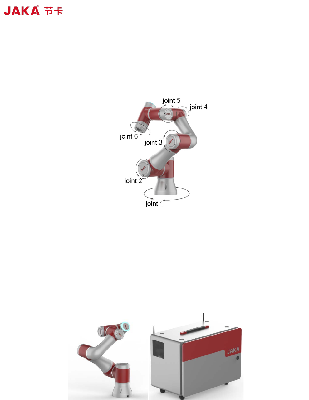
3 Mechanical Specification
The robot consists mainly of six joints and two aluminum tube arms (as shown in Fig3-1). The base is
used to install the robot, and the tool end is used to mount the tool. The tool can perform translational and
rotational movements in the robot's working range. The following sections describe the basics to be aware of
the installation of various components in the robot system.
Fig 3-1
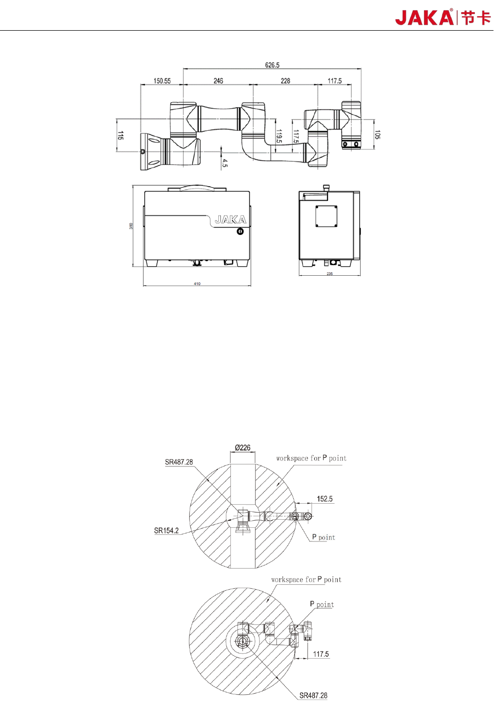
3.1 Robot Working Range
3.1.1 Robot Dimensions
The photo and dimensions of JAKA Zu 3 robot and electrical cabinet are shown in Fig 3-2 and Fig3-3.
Make sure to take into account the working range of the robot during installation to avoid injury to people or
damage to the equipment.
Fig3
-2
16 JAKA Zu 3 v1.1
Fig3-3
3.1.2 Robot Working Range
The working range of JAKA Zu 3 is shown in Fig 3-4. When choosing the robot installation position, the
cylinder space directly above and below the robot must be considered. Moving the tool close to the cylindrical
volume should be avoided if possible, because it causes the joints to move fast even though the tool is moving
slowly, causing the robot to work inefficiently and making it difficult to conduct a risk assessment.
Fig3
-4