JAKA Zu 3及JAKA Zu 3 pro-电控柜V2.1-硬件手册( 英文版).pdf - 第28页
JAKA Zu 3 v 1. 1 23 6 0V The intern al 24V po wer supply output is negative 7 V - The isolated power input is nega tive, and the factory def ault is c onnected to the i nternal GN D 9 SI2 The protec tion stop functio n i…
22 JAKA Zu 3 v1.1
3 DO11
11th digital output, PNP Type, ≤1A continuous
current output capability
4 DO12
12th digital output, PNP Type, ≤1A continuous
current output capability
5 DO13
13th digital output, PNP Type, ≤1A continuous
current output capability
6 DO14
14th digital output, PNP Type, ≤1A continuous
current output capability
7 DO15
15th digital output, PNP Type, ≤1A continuous
current output capability
8 DO16
16th digital output, PNP Type, ≤1A continuous
current output capability
9~16 V-
Isolated power input negative, default shorting is
connected to internal GND
P5 AI/O
1、4
5VA
Analog power supply 5V output, 100mA (max)
2 Ch1 Analog input/output channel 1
3 Ch2 Analog input/output channel 1
5~8 AG Analog ground
P6 HSI
1、8
5VD
Digital power supply 5V output, 100mA (max)
2、3 1P Differential signal 1 input positive / encoder A +
14、15
1N
Differential signal 1 input negative / encoder A-
4、5
2P
Differential signal 2 input positive / encoder B+
12、13 2N Differential signal 2 input negative / encoder B-
6、7
3P
Differential signal 3 input positive / encoder Z +
10、11 3N Differential signal 3 input negative / encoder Z-
9、16
DG
Digital ground
P7 -
1、2 VSB
Internal power supply 5V, 100mA (max), can be
used for remote power on/off
3 0V Internal GND (internal 24V, 12V reference ground)
4、5
485B
RS485 B
6、7
485A RS485 A
8 V-
Isolated power input negative, default shorting is
connected to internal GND
9 OFF
Remote shutdown signal input, high level (5~24V)
is valid
10 ON
Remote power-on signal input, high level (5~24V) is
valid
P8 -
1~4、8 V+
Isolated power input is positive, factory default is
connected to internal 24V
5 24V
The internal 24V output is positive and supports a
maximum of 1.5A current output
JAKA Zu
3 v1.1 23
6 0V The internal 24V power supply output is negative
7 V-
The isolated power input is negative, and the
factory default is connected to the internal GND
9 SI2
The protection stop function input 2, the factory
default is V+
10 SI1
The protection stop function input 2, the factory
default is V+
11 EI2
Emergency stop function input 2, the factory default
is V+
12 EI1
Emergency stop function input 1, the factory default
is V+.
P9 - - USB USB3.0
P10 - - Ethernet1 Gigabit Ethernet interface
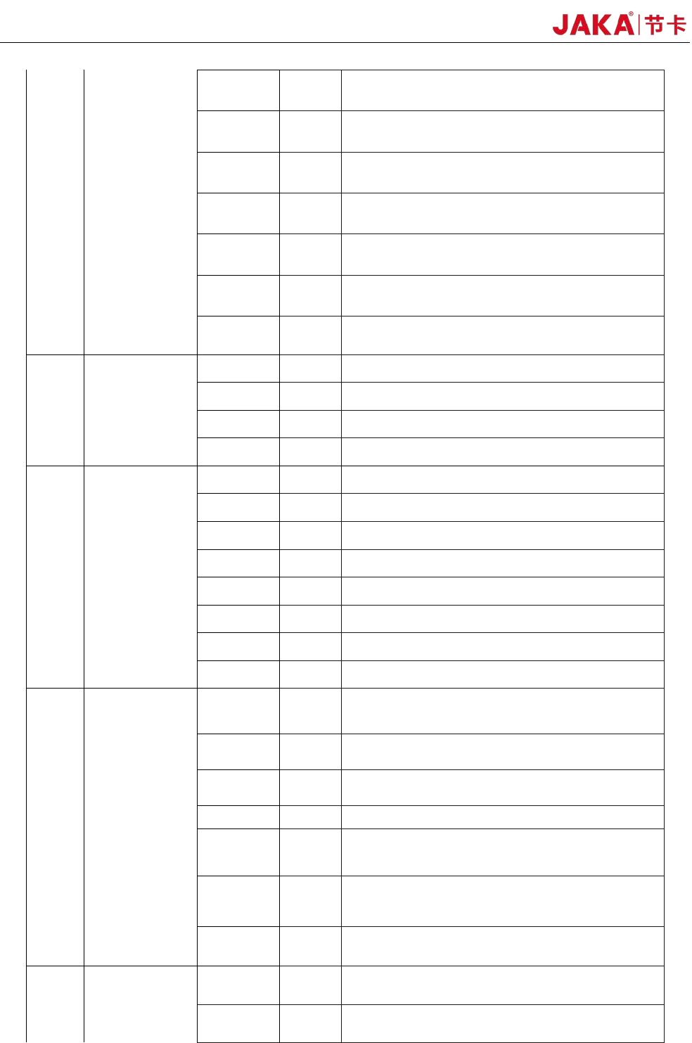
4.3.1 All digital I/O common specifications
This section describes the electrical specifications for 24V digital I/O using an electrical cabinet. Can be
divided into: V + power selection, security I / O configuration.
The electrical cabinet supports 16 digital inputs and 16 digital outputs, as shown in Figure 4-2.
Figure 4-2
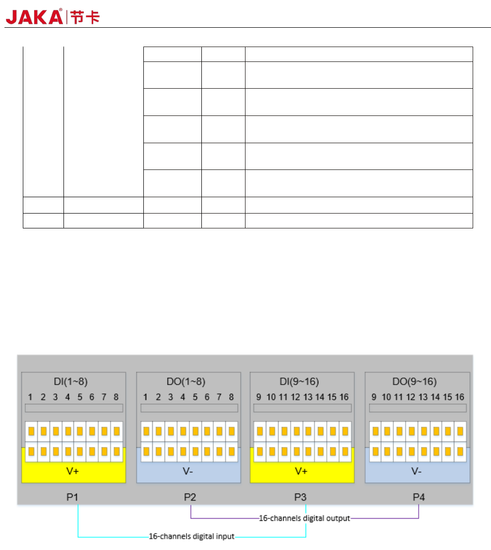
The digital I/O can be powered by a 24V power supply provided inside the control cabinet and supports
up to 1.5A output (overload will turn off the output). When the user needs more power output, the V+ power
supply can be powered by an external "24V power supply". 24V is the internal power supply and 0V is the
internal ground. V+ is the positive pole of the digital I/O interface, and V- is the negative pole of the digital I/O
interface. The factory default configuration is internal power, see Figure 4-3 below.
24 JAKA Zu 3 v1.1
V+ V-
24V
0V
P8
Internal power
supply
V+ V-
24V
0V
P8
External power
supply
+-
Figur
e 4-3
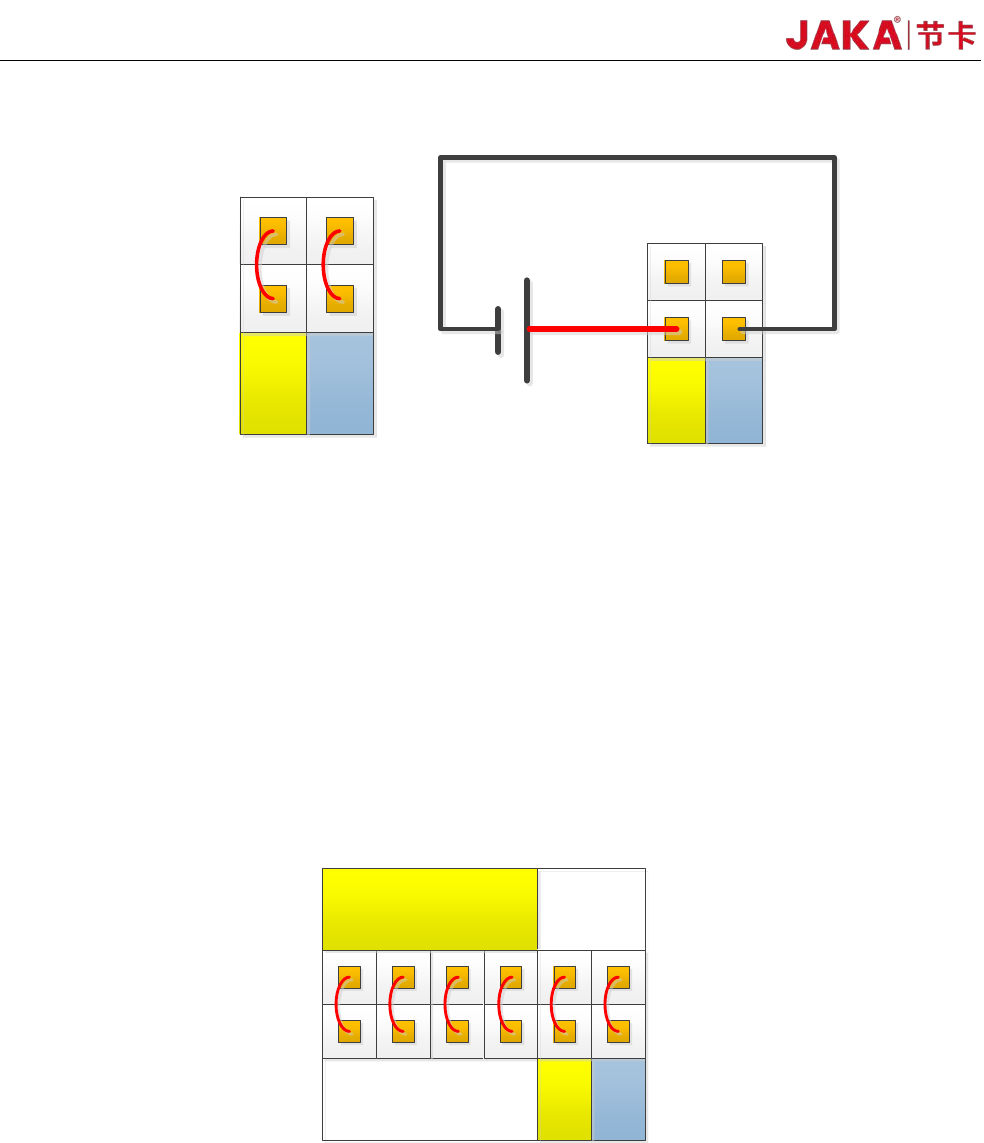
The electrical cabinet has a dedicated safety I/O interface, and the user can configure two functions:
emergency stop and protection stop. The function description is detailed in section 4.3.7. Here are some
examples of how safe I / O interface.
1. Factory configuration.
Users can use the robot without any additional safety equipment. If EI1~2 and SI1~2 are both connected
to V+, V+ is connected to 24V, and V- is connected to 0V, it indicates that 24V power is provided inside the
electrical cabinet. As shown in Figure 4-4.
24V
0V
P8
EI
1 2
SI
1 2
V+
V+ V-
0V
24V
P8
Figur
e 4-4
2、Connect the emergency stop switch.
The user needs to use one or more additional emergency stop or guard stop switches, please refer to
Figure 4-5 and Figure 4-6 for wiring. Figure 4-5 and Figure 4-6 show how to use one or more emergency stop
switches.
The example uses an internal 24V power supply and the user can also use an external 24V power
suppl
y.