JAKA Zu 3及JAKA Zu 3 pro-电控柜V2.1-硬件手册( 英文版).pdf - 第40页
JAKA Zu 3 v 1. 1 35 5 Maintenance and Repair Maintenanc e and r epairing must be perf ormed in complianc e with al l safety instr uctions in this m anual. Repairin g must be perform ed by an a uthorized s ystem int egrat…
34 JAKA Zu 3 v1.1
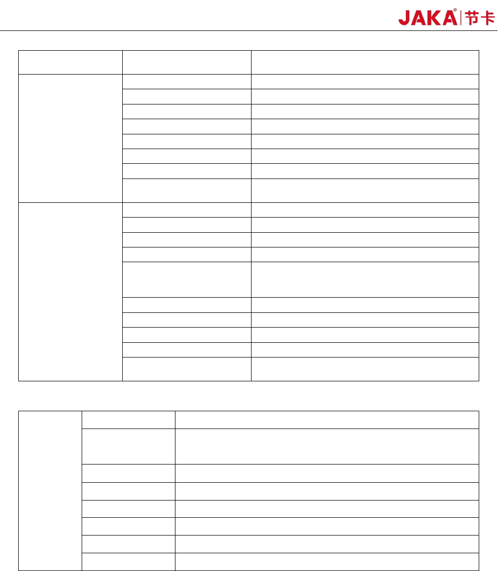
Collaborative operation
Cooperative operation according to
GB11291.1-2011standard
Working range and
speed
Robot joint Working range Max speed
Joint1 ±270° 180°/s
Joint 2 -85°、+265° 180°/s
Joint 3 ±175° 180°/s
Joint 4 -85°,+265° 180°/s
Joint 5 ±270° 180°/s
Joint 6 ±270° 180°/s
Maximum speed of the
tool end
/ 1.5m/s
Physical properties
and others
Power consumption Average 150W
Temperature 0-50°C
IPclassification IP54
Robot installation posture Install at any angle.
TIO Ports
2 digital input
2 digital output
1 analog input
TIO Power 24V
Base diameter 129mm
Material Aluminum alloy, PC
TIOSize M8
Robot connection cable
length
6m
2.Electrical cabinet technical specifications:
Electrical
cabinet
IP classification IP44
I/Oports
16 digital input
16 digital output
2 analog input/output
I/O power 24V
Communication TCP/IP, Modbus TCP, Modbus RTU
Power 100-240VAC,50-60Hz
Size 410*307*235(mm)(W*H*D)
Weight 12kg
Material Stainless steel alloy
JAKA Zu
3 v1.1 35
5 Maintenance and Repair
Maintenance and repairing must be performed in compliance with all safety instructions in this manual.
Repairing must be performed by an authorized system integrator or JAKA staff.
Parts returned to JAKA should be returned as specified in the Service Manual.。
5.1 Safety Instructions
After maintenance and repair, product must be checked to ensure the required safety level.The valid
national or regional work safety regulations must be observed for this check.The correct functioning of all
safety functions shall also be tested.
The purpose of maintenance and repairing is to ensure that the system is kept operational or, in the event
of a fault, to return the system to an operational state. Repairing includes troubleshooting in addition to the
actual repair itself.
The following safety procedures and warnings must be observed during the operation of the robot or
electrical cabinet:
DANGER:
1. Do not change anything in the safety configuration of the software. If any
safety parameter is changed, the complete robot system shall be considered
as a new system, which means that the overall safety approval process,
including risk assessment, shall be updated accordingly.
2. Replace faulty components using new components with the same article
numbers or equivalent components approved by JAKA for this purpose.
3. Reactivate any deactivated safety measures immediately after the work
is completed.
4. Document all repairs and save this documentation in the technical file
associated with the complete robot system.。
DANGER:
1. Remove the main input cable from the bottom of the electrical cabinet to
ensure that it is completely unpowered. Deenergize any other source of energy
connected to the robot arm or control box. Take necessary precautions to
prevent other persons from powering on the system during the repair period.
2. Check the earth connection before re-opening the system.
3. Observe ESD regulations during the disassembly of the parts of the robot
or electrical cabinet.
4. Avoid disassembling the power supply inside the electrical cabinet. High
voltages can be present inside these power supplies for several hours after the
electrical cabinet has been switched off.
5. Prevent water and dust from entering the robot or electrical cabinet.
36 JAKA Zu 3 v1.1
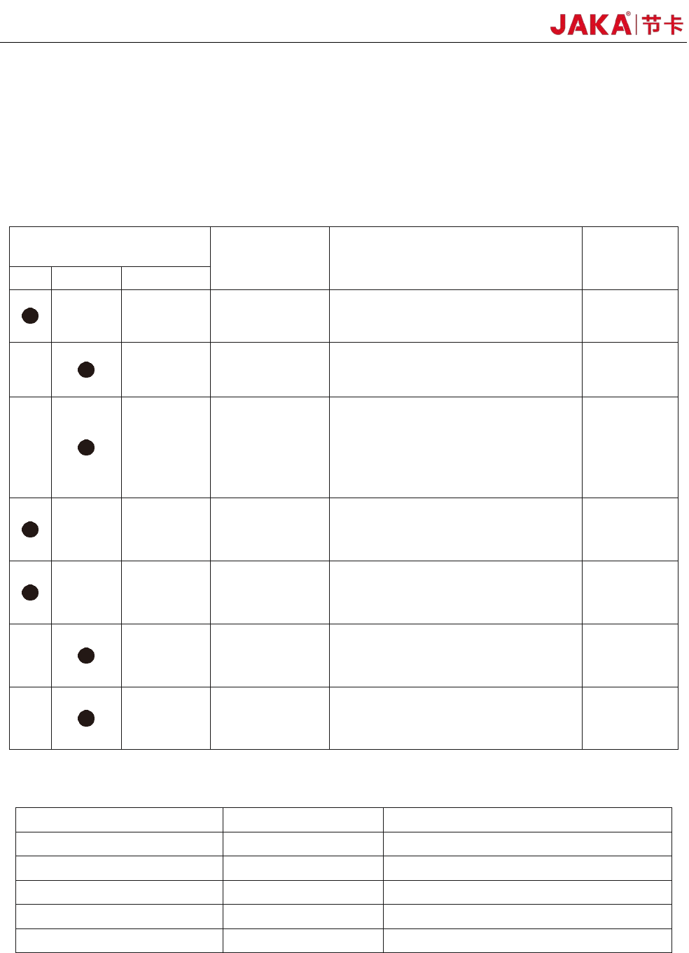
5.2 Overhaul Project and Cycle
In order for the robot to maintain high performance for a long time, a maintenance check must be carried
out. The person in charge of overhaul must prepare an overhaul plan and carry out an inspection. Please refer
to the table below for overhaul items.
In addition, overhauls are required every 20,000 hours of operation time or every 4 years. If you are not
clear about the maintenance processes, please contact our service department.
Cycle
Overhaul Items Overhaul essentials Part
daily 3month Every year
Robot body
confirm that whether the stored
location of the program is deviated
All Parts
Cleaning the
robot body
Wipe
off dirt, etc., remove
accumulated spatter, ash, dust,
cutting residue, etc.
All Parts
Main bolts
All the bolts exposed on the
outside of the robot need to be
tightened and marked (see the
specified tightening torque table),
including the tool mounting bolts
are also implemented.
All Parts
Motor
Abnormal heating or sound
confirmation
All Axis
Brake
Check when the servo power is
turned ON/OFF, whether the robot
arm or tool will fall.
All Axis
Reducer
Check for abnormal vibration, noise,
and oil leakage
All Axis
Tools
Apply force to the tool to make sure
it is properly and securely bolted in place.
The 6th Axis
Bolted tightening torque table
Bolt Size He
xagon bolt SUS bolt with hexagon hole
M3 2.4 Nm 1.47 Nm
M4 5.4 Nm 3.4 Nm
M5 9 Nm 6.9 Nm
M6 15.3 Nm 11.8 Nm
M8 37 Nm 28.4 Nm
Th
e tightening torques will vary depending on the type of base metal or bolt. When not
specified, please follow the tightening torques above.