JAKA Zu 3及JAKA Zu 3 pro-电控柜V2.1-硬件手册( 英文版).pdf - 第21页
16 JAKA Zu 3 v1. 1 Fig 3-3 3.1.2 Rob ot W orking Range The worki ng range of JAKA Zu 3 is s hown in F ig 3 - 4. When cho osing the robot in stallati on position, the cylinder s pace dir ectly abo ve and be low the ro bot…
JAKA Zu
3 v1.1 15
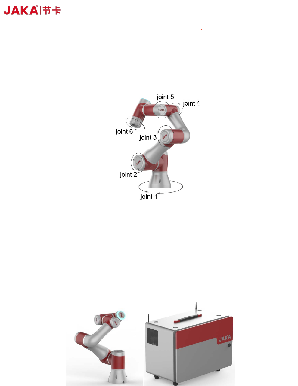
3 Mechanical Specification
The robot consists mainly of six joints and two aluminum tube arms (as shown in Fig3-1). The base is
used to install the robot, and the tool end is used to mount the tool. The tool can perform translational and
rotational movements in the robot's working range. The following sections describe the basics to be aware of
the installation of various components in the robot system.
Fig 3-1
3.1 Robot Working Range
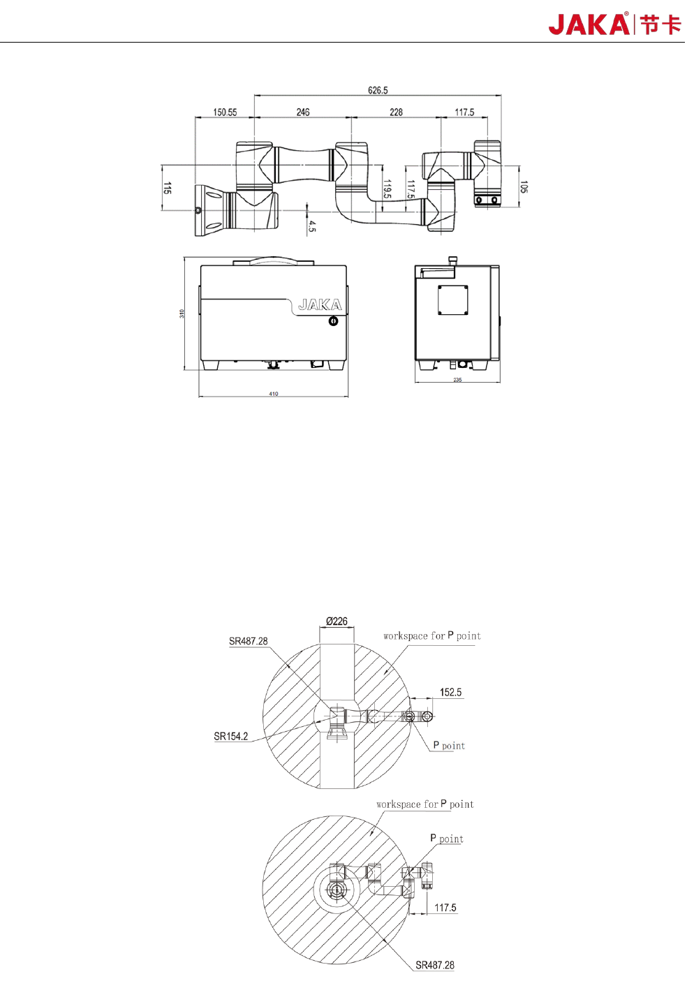
3.1.1 Robot Dimensions
The photo and dimensions of JAKA Zu 3 robot and electrical cabinet are shown in Fig 3-2 and Fig3-3.
Make sure to take into account the working range of the robot during installation to avoid injury to people or
damage to the equipment.
Fig3
-2
16 JAKA Zu 3 v1.1
Fig3-3
3.1.2 Robot Working Range
The working range of JAKA Zu 3 is shown in Fig 3-4. When choosing the robot installation position, the
cylinder space directly above and below the robot must be considered. Moving the tool close to the cylindrical
volume should be avoided if possible, because it causes the joints to move fast even though the tool is moving
slowly, causing the robot to work inefficiently and making it difficult to conduct a risk assessment.
Fig3
-4
JAKA Zu
3 v1.1
17
3.2 Installation
3.2.1 General installation steps
1.Determine the working range of the robot;
2.Mount the robot on the base;
3.Install the required tools at the end of the robot.
3.2.2 Important safety instructions
DANGE
R:
1. Make sure the robot is properly and securely bolted in place.
2.
The mounting surface must be shockproof and sturdy.
DANGE
R:
1. Make sure the tool is properly and securely bolted in place.
2. Make sure that the tool is constructed such that it cannot
create a hazardous situation by dropping a part unexpectedly.
DANGER:
1. Make sure that the electrical cabinet and cables do not come
into contact with liquids. A wet electrical cabinet could cause
death.
2. The electrical cabinet must not be exposed to dusty or wet
environments that exceed IP20 rating. Pay special attention to
environments with conductive dust.
CAUT
IONS:
If the robot is bathed in water over an extended time period it might be damaged. The robot should not be
mounted in water or in a wet environment.
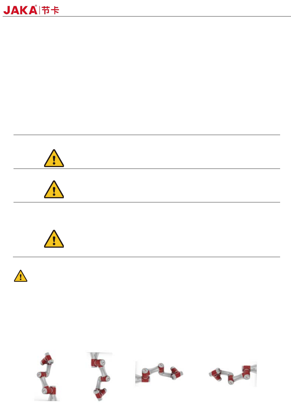
3.2.3 Robot Body Installation
The robot has an attitude and position adaptation function. It can be mounted in various ways, such
as ground, wall, and celling mounting. As shown in Fig 3-5:
Fig
3-5
Using four M8 bolts to mount the robot through the four 9mm through holes on the robot base. It is