JAKA Zu 3及JAKA Zu 3 pro-电控柜V2.1-硬件手册( 英文版).pdf - 第37页
32 JAKA Zu 3 v1. 1 3 DI2 I gree n Digital i nput 2. N PN type . O ptocoupler Cathode input. I nternal connect4. 7k resistor . 4 DO1 O yello w Digital ou tput 1. N PN type . Open Drain output. Cur rent ≤0.5A per chan nel.…
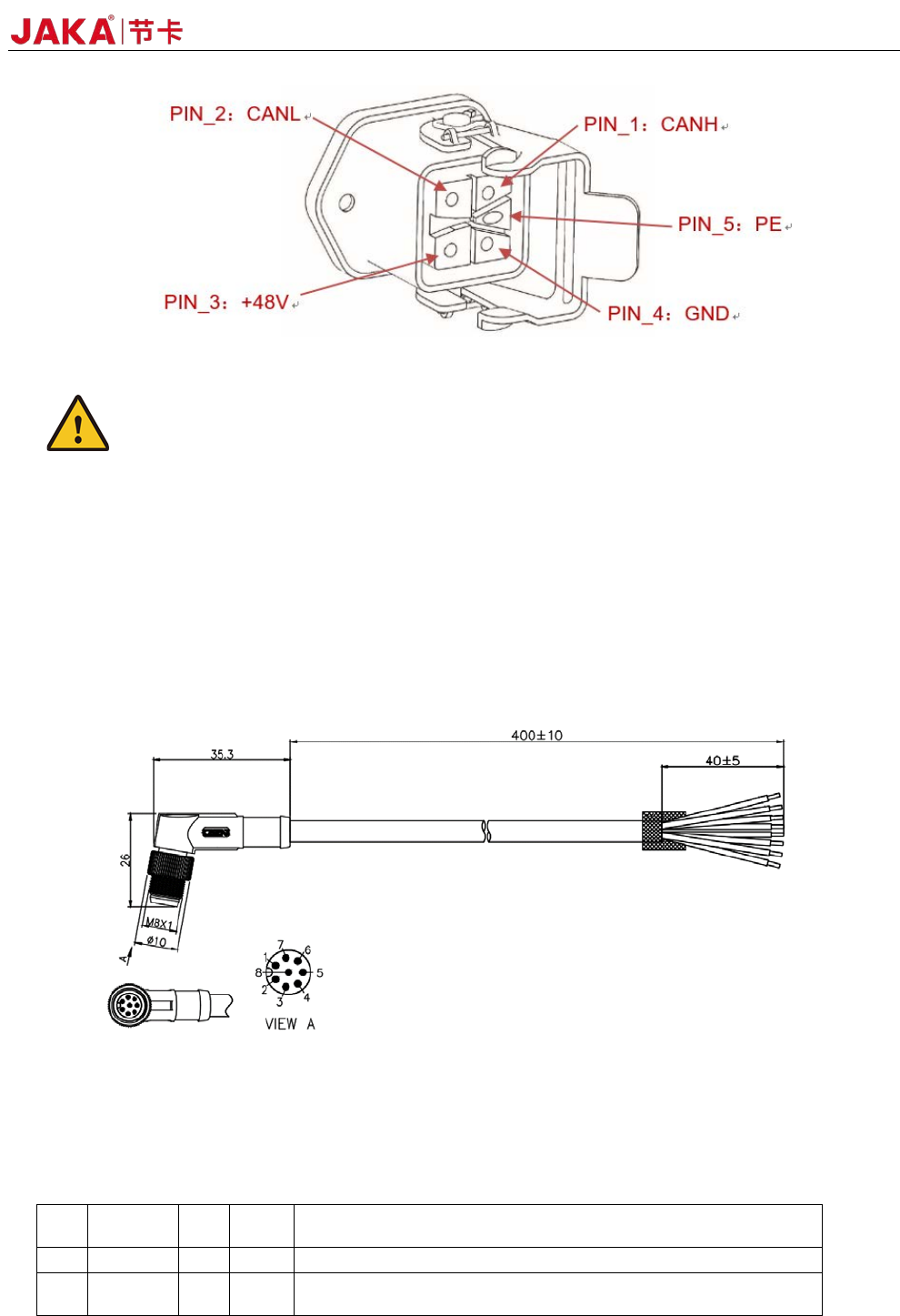
JAKA Zu
3 v1.1 31
Fi
gure 4-16
Caution:
1.Do not disconnect the robot cable when the robot is turned on.
2.Do not extend or modify the original cable.
4.5 Tool Input and Output
The tool input and output position is on the side of the robot tool flange. Includes two digital inputs, two
digital outputs and one analog input.
If the customer needs to choose the TIO external cable, please call 400-006-2665. Figure 4-17 shows the
cable specifications.
Fi
gure 4-17 Cable specifications
4.5.1TIO function description
The TIO interface function is described in the following table:
PIN DEFINE I/O
Line
color
DESCRIPTION
1 +24V -
red 24V positive. Maximum continuous current to 1.0A
2 DI1 I
blue Digital input 1. NPN type. Optocoupler Cathode input. Internal
connect4.7k resistor.
32 JAKA Zu 3 v1.1
3 DI2 I
gree
n
Digital input 2. NPN type. Optocoupler Cathode input. Internal
connect4.7k resistor.
4 DO1 O
yello
w
Digital output 1. NPN type. Open Drain output. Current ≤0.5A
per channel.
5 DO2 O
Pink Digital output 2. NPN type. Open Drain output. Current ≤0.5A
per channel.
6 AIN_P I
brow
n
Anolog input.Supports -10V~+10V voltage input. Decouple with
the AIN_N pin.
7 AIN_N I
white Anolog input:Negative. Decouple with the AIN_P pin.
8 GND -
gray GND. 24V Power Ground.
1. TIO anolog input interface
Analog input AI1 supports -10V~+10V high precision voltage range input.
2. TIO digital input interface
The digital input uses the optocoupler cathode input and is active low. Internally connected 4.7k resistors.
Fi
gure 4-18
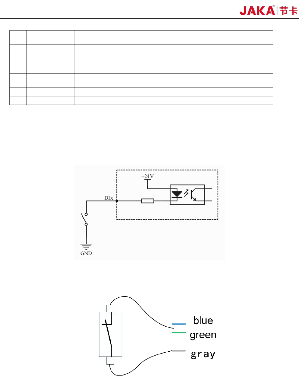
a)Type of the dry contact input:
Fi
gure 4-19
The dry contact input (ie, switch input) is connected to the negative pole of the 24V power supply in TIO
(gray wire), and the other end is connected to the DI digital input (blue or green wire), as shown in Figure 4-
19.
b) The input type is NPN
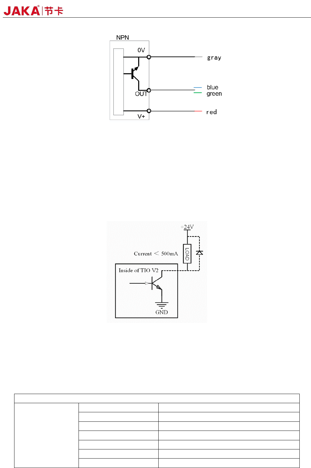
JAKA Zu
3 v1.1 33
Fi
gure 4-20
Figure 4-20 shows the block diagram of the NPN input device connection: the V + pin is connected to +
24V (red wire), the 0V pin is connected to the negative pole (gray wire), and the OUT pin is connected to DIx
(blue or green wire).
3. TIO digital output interface
The digital output interface uses an open collector output that supports up to 500mA of current capability.
Note: If an inductive load (such as a relay, electromagnet, DC motor, etc.) requires an external
freewheeling diode.
Figure 4-21
* Note: It is strongly recommended to use protection DIODES for the inductive loads (such as relays,
electromagnets, DC motors, etc.). Otherwise, this port may damage the hardware circuit
4.6 Technical Specifications
1.JAKA Zu
®
3 Robot Technical Specifications:
Robot type: JAKA Zu 3
Product Features
Maximum payload 3kg
Weight (including cable) 12kg
Working radius 626mm
Repeatability <±0.03mm
Degrees of freedom 6
Programming Graphical drag-and-drop programmin
FlexPendant Type Mobile device (PAD/mobile)