JAKA Zu 3及JAKA Zu 3 pro-电控柜V2.1-硬件手册( 英文版).pdf - 第25页
20 JAKA Zu 3 v1. 1 Cautions: 1. The robot has pass ed the electroma gnetic co mpatibil ity test specified in the CR certificatio n. Exceeding standard interf erence signals wi ll cause abn ormal behav ior of the ro bot. …
JAKA Zu
3 v1.1 19
4 Electrical Interface
4.1 Introduction
This chapter describes all the electrical interfaces of the robot and electrical cabinet.
These interfaces are divided into three categories, each of which has different purposes and properties:
• Front panel interface of the electrical cabinet
• Bottom interface of the electrical cabinet
• Tool input and output interface(TIO)
These three types of interfaces are described below, and most types of I/O are provided with examples.
4.2 Warnings and Cautions
Be sure to observe the following warnings and cautions when designing and installing robotic
applications. These warnings and cautions are also apply for service work.
Warning:
1.Never connect a safety signal to a non-safety PLC with an
unsuitable safety level. Failure to follow this warning may result in
serious injury or death due to the failure of a safety stop function.
Be sure to separate the safety interface signal from the normal
I/O interface signal.
2.All safety signals are redundant (two independent channels).
Keeping the two channels independent ensures that no safety
features are lost in the event of a single failure.
3. For an introduction to the I/O functions inside the electrical
cabinet, please refer to Section 4.3.
Warning:
1. Please ensure that all equipment that is not wet is kept dry. If
water enters the
product, cut off the power supply in a timely
manner, then contact your supplier.
2. Use only the original cable of the robot. Do not use the robot in
applications where the cable needs to be bent. If you need a longer
cable or flexible cable, you can contact your supplier.
3. For protective earthing (PE), use the screw connector marked
with a grounding mark in the electrical cabinet. The ground
connector should have at least the rated current of the current
maximum within the system.
4. When the cabinet's I / O interface cable when installed, the door
is opened to remove the metal plate outlet holes, and to ensure
that I / O cable outlet holes to avoid fraying.
20 JAKA Zu 3 v1.1
Cautions:
1. The robot has passed the electromagnetic compatibility test
specified in the CR certification. Exceeding standard interference
signals will cause abnormal behavior of the robot. Extremely high
signal levels or exceeding the maximum standards will cause
permanent damage to the robot. JAKA is not responsible for any
damage caused by out-of-range EMC problems.
2. The length of the I/O cable used to connect the electrical cabinet
to other mechanical and industrial equipment must not exceed 30
meters unless it is feasible after extended testing and shielded
cables are required if necessary.
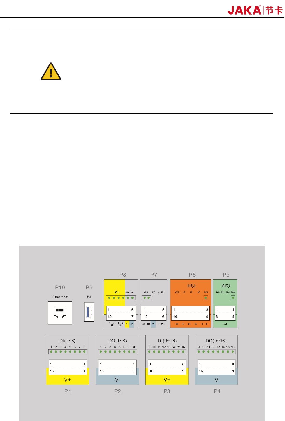
4.3 Front panel of the electrical cabinet
The front panel interface of the electrical cabinet is arranged on the first floor after the electrical cabinet
door is opened, including:
16 digital inputs (P1 and P3)
16 digital outputs (P2 and P4)
2 configurable analog interfaces (P5)
1 set of high speed interface (P6)
Remote ON/OFF and 485 interface (P7)
Safety function interface (P8)
USB3.0 interface (P9) and Ethernet interface (P10)
The USB interface and Ethernet interface are reserved for internal use and can be contacted by JAKA
technical support personnel if needed. The layout is shown in Figure 4-1.
Fi
gure 4-1 Front panel interface of the electrical cabinet
JAKA Zu
3 v1.1 21
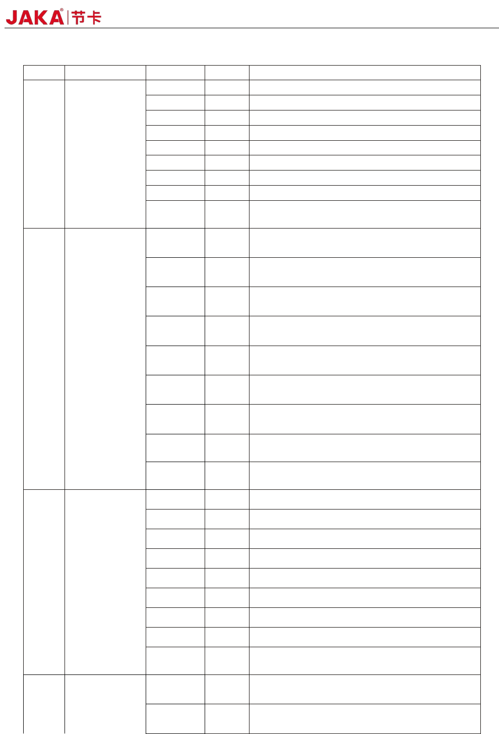
Electrical control cabinet front panel interface definition table:
Index Name PIN Label Description
P1
DI(1~8)
Digital Input
1 DI1 1st digital input, PNP Type, the input is active high
2 DI2 2nd digital input, PNP Type, the input is active high
3 DI3 3rd digital input, PNP type, the input is active high
4 DI4 4th digital input, PNP Type, the input is active high
5 DI5 5th digital input, PNP Type, the input is active high
6 DI6 6th digital input, PNP Type, the input is active high
7 DI7 7th digital input, PNP type, the input is active high
8 DI8 8th digital input, PNP type, the input is active high
9~16 V+
The isolated power input is positive, and the factory
default is 24V internal.
P2
DO(1~8)
Digital Output
1 DO1
1st digital output, PNP Type, ≤1A continuous
current output capability
2 DO2
2nd digital output, PNP Type, ≤1A continuous
current output capability
3 DO3
3rd digital output, PNP Type, ≤1A continuous
current output capability
4 DO4
4th digital output, PNP Type, ≤1A continuous
current output capability
5 DO5
5th digital output, PNP Type, ≤1A continuous
current output capability
6 DO6
6th digital output, PNP Type, ≤1A continuous
current output capability
7 DO7
7th digital output, PNP Type, ≤1A continuous
current output capability
8 DO8
8th digital output, PNP Type, ≤1A continuous
current output capability
9~16 V-
Isolated power input negative, default shorting is
connected to internal GND
P3
DI(9~16)
Digital Input
1 DI9
9th digital input, PNP Type, the input is active high
2 DI10 10th digital input, PNP Type, the input is active high
3 DI11 11th digital input, PNP Type, the input is active high
4 DI12 12th digital input, PNP Type, the input is active high
5 DI13 13th digital input, PNP Type, the input is active high
6 DI14 14th digital input, PNP Type, the input is active high
7 DI15 15th digital input, PNP Type, the input is active high
8 DI16 16th digital input, PNP Type, the input is active high
9~16 V+
The isolated power input is positive, and the factory
default is 24V internal
P4
DO(9~16)
Digital Output
1 DO9
9th digital output, PNP Type, ≤1A continuous
current output capability
2 DO10
10th digital output, PNP Type, ≤1A continuous
current output capability