JAKA Zu 3及JAKA Zu 3 pro-电控柜V2.1-硬件手册( 英文版).pdf - 第34页
JAKA Zu 3 v 1. 1 29 • Use th e same GND f or equip ment and e lectrica l cabi net. The analo g AI/O is not isolated from the electrica l control ca binet. • Use shi elded cabl es or twis ted pairs. C onnect t he shield t…
28 JAKA Zu 3 v1.1
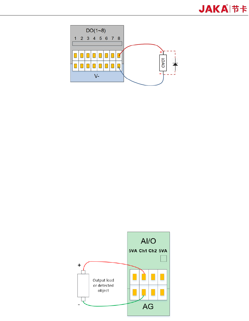
Fig 4-13
The digital output module can be controlled by the DO function of the APP. The user needs to
control the load power when using it. The single channel should not exceed 1A current, and the DO
output current should not exceed the maximum output current of the power supply.
* Note: It is strongly recommended to use protection DIODES for the inductive loads (such as
relays, electromagnets, DC motors, etc.).
4.3.4 Analog Input&Output(AI&AO)
The electrical cabinet has 2 analog input and output interfaces (Ch1, Ch2), the input mode can be
configured, and the AI mode is as follows:
1) Current signal input: 4 to 20 mA.
2) Voltage signal input: 0~5V, 0~10V, -10V~+10V.
3) Current signal output: 0~20mA
4) Voltage signal output: 0~5V, 0~10V, -10V~+10V.
The wiring method for analog input and output is shown in Figure 4-13.
Fi
gure 4-14
The JAKA CAB V2 AI/O interface can be configured to work in different modes (factory default is
0~10V analog input). The user can set the AI/O working mode through the APP.
For high accuracy, the following instructions are recommended:
• Use the AG terminal closest to the AI/O.

JAKA Zu
3 v1.1 29
• Use the same GND for equipment and electrical cabinet. The analog AI/O is not isolated from the
electrical control cabinet.
• Use shielded cables or twisted pairs. Connect the shield to the "AG" on the "Power".
• The sensitivity of the current signal is lower for the device operating in current mode than the
interface.
4.3.5 High Speed Interface
The P6 HSI (High Speed Interface) can be connected to an external encoder. Can be used for conveyor
tracking and other occasions. For detailed usage, please contact our technical staff for support.
4.3.6 Remote ON/OFF
The remote ON/OFF control is used to enable the user to leave the APP and the handle to turn the
cabinet on and off. It can usually remotely control the on/off switch of the robotic control cabinet when the user
connects to the PLC system.
When ON/OFF receives a 5~24V voltage signal (reference ground is V-), and the “ON/OFF” connector
functions the same as the handle switch button
The user can short-circuit Remote ON/OFF to 12V power supply or VSB interface through the switch.
4.3.7 Safety I/O
In order to ensure the safety function configuration of the robot, the electrical cabinet provides two fixed
safety function input interfaces. EI is an emergency stop and SI is the user stop. Both EI and SI have a redundant
design that can be enabled when any channel signal is active. The emergency stop function is similar to the
handle emergency stop button function, and the user stop function belongs to the program pause. The difference
between the two functions is as follows:
EI SI
Robot stops moving Yes Yes
Joint motor status Stop Enable
Robot power supply OFF ON
Program execution
status
Terminated Pause
Brake status OFF ON
Users can access security doors, security light curtains, sensors and other devices according to actual
security requirements.
4.4 Bottom panel of the electrical cabinet
The bottom panel of the electrical cabinet includes the outlet hole, the binding hole, the handle outlet, the
Ethernet interface, the robot heavy-duty connector, the standard plug and the switch.
The outlet holes and the tie holes can be used to arrange and fix the wire harness leading to the front
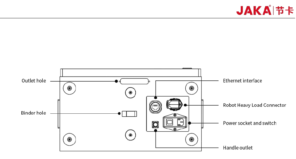
30 JAKA Zu 3 v1.1
panel of the robot. The Ethernet interface is used to connect the robot to the local network. The word plug and
switch are used for power connection. The robot heavy-duty connector is used to connect the electric control
cabinet to the robot body.
Fi
gure 4-15 Electrical cabinet bottom panel interface
4.4.1 Power Connection
The robot power cable is supplied with the robot. One end of the power cord is plugged into the socket of
the bottom panel of the electric control cabinet. The other end of the power cord is a triangular plug that plugs
into the corresponding mains socket according to the safety assessment specification. The socket has a
switch and a fuse. The socket switch is limited to use when the robot is turned off. The purpose of the outlet
switch is to completely disconnect the robot power supply. The type of fuses included in the switch should be
selected according to the working conditions of the robot. It is configured to be 10A at the factory.
The power source used by the robot should be equipped with at least:
• grounding
• mains fuse
• Residual current circuit breaker
It is recommended to install a power switch for the power supply of all devices in the robot's environment.
Warning:
1. Make sure that the robot is grounded correctly (Electrical connection to earth).
2. Make sure that the input power to the electrical cabinet is protected with a RCD (Residual Current
Device) and a correct fuse.
3. Lockout and tagout all power for the complete robot installation during service. Other equipment shall
not supply voltage to the robot when the system is locked out.
4. Make sure that all cables are connected correctly before the electrical canbinet is powered. Always use
an original and correct power cord.
4.4.2 Robot Connection
Be sure to connect the robot to the control cabinet using the robotic connection cable provided by JAKA.
Be sure to lock the connector before starting the robot. Before disconnecting the cable robot, the robot must
cut off the power supply. Figure 4-16 shows the interface definition of heavy duty connector.