JAKA Zu 3及JAKA Zu 3 pro-电控柜V2.1-硬件手册( 英文版).pdf - 第36页
JAKA Zu 3 v 1. 1 31 Fi gure 4 -16 Caution: 1.Do not disconnec t the rob ot cable when the robot is turned on. 2.Do not extend or m odify t he origina l cable. 4.5 T ool Input a nd Output The tool input and output p ositi…
30 JAKA Zu 3 v1.1
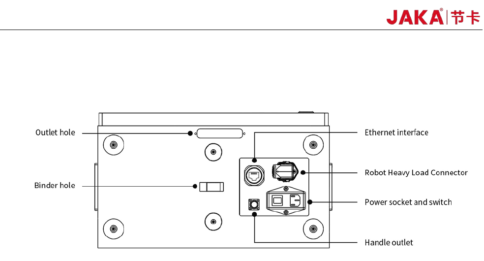
panel of the robot. The Ethernet interface is used to connect the robot to the local network. The word plug and
switch are used for power connection. The robot heavy-duty connector is used to connect the electric control
cabinet to the robot body.
Fi
gure 4-15 Electrical cabinet bottom panel interface
4.4.1 Power Connection
The robot power cable is supplied with the robot. One end of the power cord is plugged into the socket of
the bottom panel of the electric control cabinet. The other end of the power cord is a triangular plug that plugs
into the corresponding mains socket according to the safety assessment specification. The socket has a
switch and a fuse. The socket switch is limited to use when the robot is turned off. The purpose of the outlet
switch is to completely disconnect the robot power supply. The type of fuses included in the switch should be
selected according to the working conditions of the robot. It is configured to be 10A at the factory.
The power source used by the robot should be equipped with at least:
• grounding
• mains fuse
• Residual current circuit breaker
It is recommended to install a power switch for the power supply of all devices in the robot's environment.
Warning:
1. Make sure that the robot is grounded correctly (Electrical connection to earth).
2. Make sure that the input power to the electrical cabinet is protected with a RCD (Residual Current
Device) and a correct fuse.
3. Lockout and tagout all power for the complete robot installation during service. Other equipment shall
not supply voltage to the robot when the system is locked out.
4. Make sure that all cables are connected correctly before the electrical canbinet is powered. Always use
an original and correct power cord.
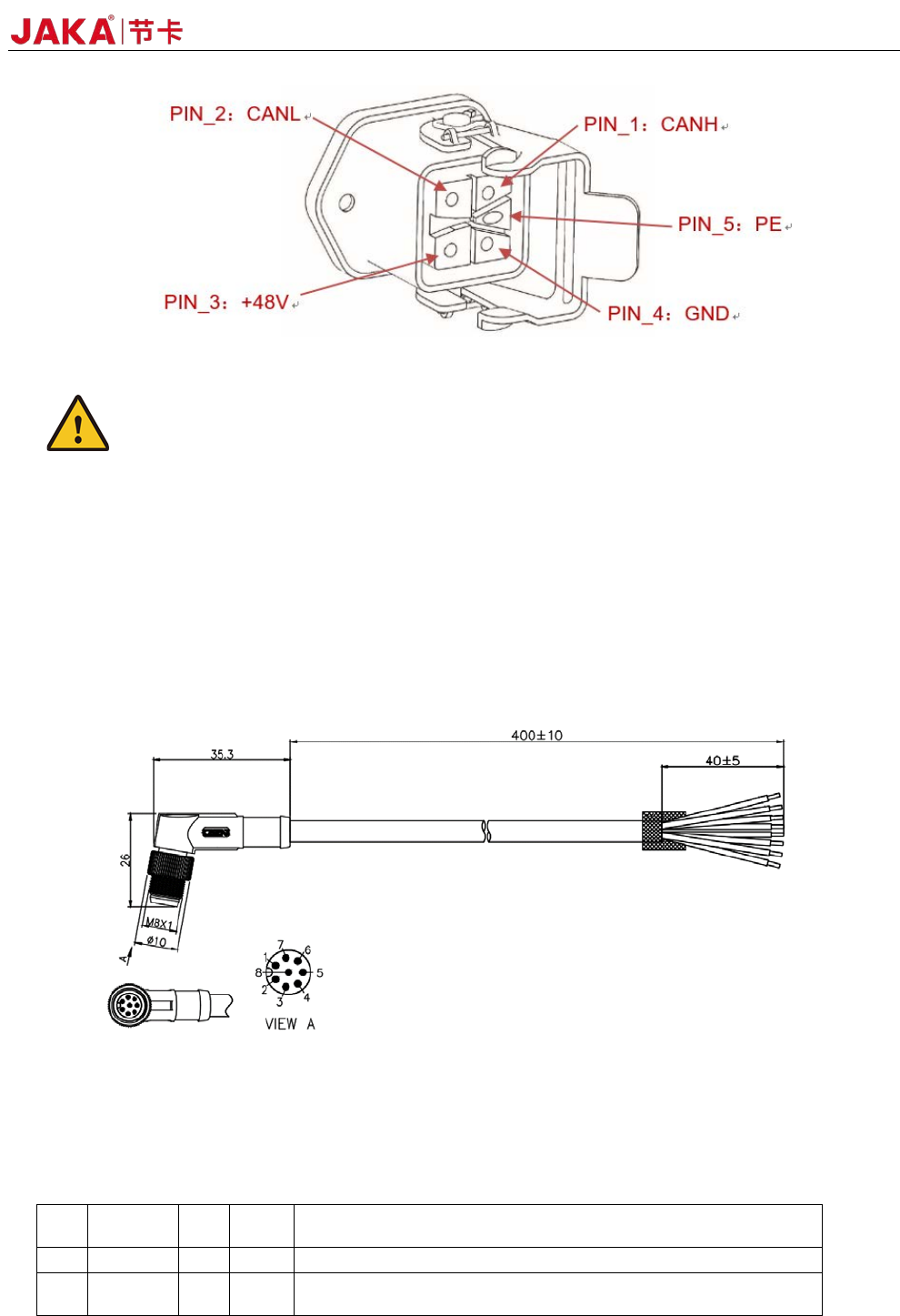
4.4.2 Robot Connection
Be sure to connect the robot to the control cabinet using the robotic connection cable provided by JAKA.
Be sure to lock the connector before starting the robot. Before disconnecting the cable robot, the robot must
cut off the power supply. Figure 4-16 shows the interface definition of heavy duty connector.
JAKA Zu
3 v1.1 31
Fi
gure 4-16
Caution:
1.Do not disconnect the robot cable when the robot is turned on.
2.Do not extend or modify the original cable.
4.5 Tool Input and Output
The tool input and output position is on the side of the robot tool flange. Includes two digital inputs, two
digital outputs and one analog input.
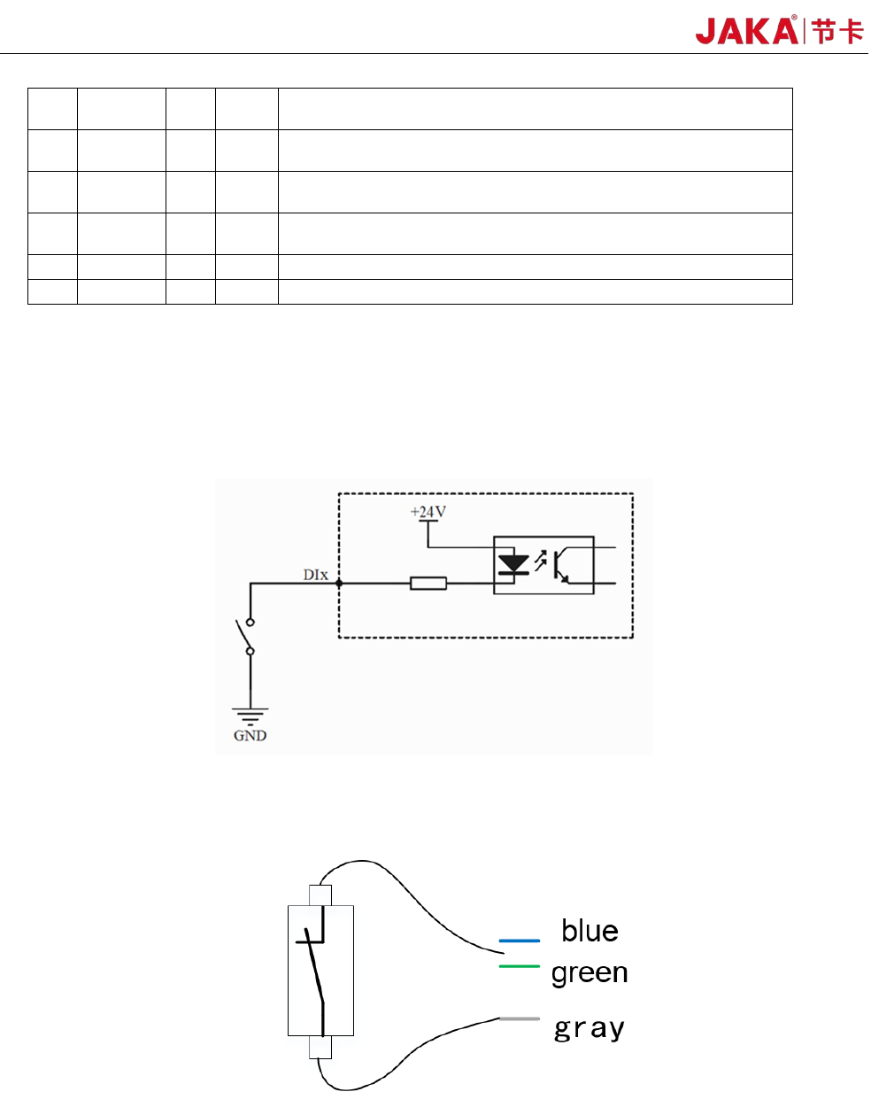
If the customer needs to choose the TIO external cable, please call 400-006-2665. Figure 4-17 shows the
cable specifications.
Fi
gure 4-17 Cable specifications
4.5.1TIO function description
The TIO interface function is described in the following table:
PIN DEFINE I/O
Line
color
DESCRIPTION
1 +24V -
red 24V positive. Maximum continuous current to 1.0A
2 DI1 I
blue Digital input 1. NPN type. Optocoupler Cathode input. Internal
connect4.7k resistor.
32 JAKA Zu 3 v1.1
3 DI2 I
gree
n
Digital input 2. NPN type. Optocoupler Cathode input. Internal
connect4.7k resistor.
4 DO1 O
yello
w
Digital output 1. NPN type. Open Drain output. Current ≤0.5A
per channel.
5 DO2 O
Pink Digital output 2. NPN type. Open Drain output. Current ≤0.5A
per channel.
6 AIN_P I
brow
n
Anolog input.Supports -10V~+10V voltage input. Decouple with
the AIN_N pin.
7 AIN_N I
white Anolog input:Negative. Decouple with the AIN_P pin.
8 GND -
gray GND. 24V Power Ground.
1. TIO anolog input interface
Analog input AI1 supports -10V~+10V high precision voltage range input.
2. TIO digital input interface
The digital input uses the optocoupler cathode input and is active low. Internally connected 4.7k resistors.
Fi
gure 4-18
a)Type of the dry contact input:
Fi
gure 4-19
The dry contact input (ie, switch input) is connected to the negative pole of the 24V power supply in TIO
(gray wire), and the other end is connected to the DI digital input (blue or green wire), as shown in Figure 4-
19.
b) The input type is NPN