JAKA Zu 3及JAKA Zu 3 pro-电控柜V2.1-硬件手册( 英文版).pdf - 第31页
26 JAKA Zu 3 v1. 1 4.3.2 Dig ital Input (D I) Fig 4-8 The electr ical cab inet is eq uipped wit h 16 digi tal PNP ty pe input(Ac tive high) (DI1 ~ DI 16) to support isolated s ignal in put. The level sig nal satisf ies t…
JAKA Zu
3 v1.1 25
24V
0V
P8
Emergency stop
switch-Single switch
EI
1 2
SI
1 2
V+
V+ V-
0V
24V
P8
Fi
gure 4-5
24V
0V
P8
Emergency stop -
multi-way switch
EI
1 2
SI
1 2
V+
V+ V-
0V
24V
P8
Fi
gure 4-6
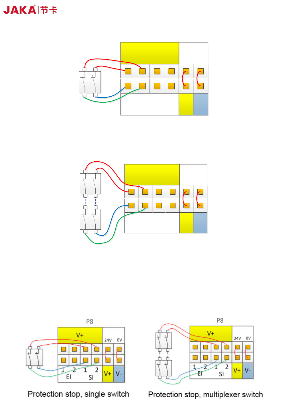
3. Connect the protective stop switch
Protective stop function, support automatic recovery. The electrical cabinet door switch is an application
case of the protection stop device, and the robot stops when the electrical cabinet door is opened. The wiring
diagram is shown in Figure 4-7.
Fig
4-7
26 JAKA Zu 3 v1.1
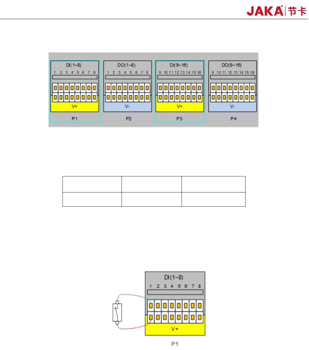
4.3.2 Digital Input (DI)
Fig
4-8
The electrical cabinet is equipped with 16 digital PNP type input(Active high) (DI1 ~ DI16) to support
isolated signal input. The level signal satisfies the IEC61131-2 (Type1/2/3) standard and is used to detect the
input signal level status.
V+ Voltage
Low range High range
24V
0~11V 15~24V
The V+ interface supports external 10~35V power input. The factory default uses internal 24V power
supply. The high level range is 15~24V, and the low level range is 0~11V.
Users can also connect DIx to V+ directly.
Different types of input signals have
different connections. The specific connection methods are as
follows:
a) Dry contact signal as input
Figure 4-9
During dry contact input, one of the wires is connected to V + and the other wire is connected to DIx.
When the circuit is on (as shown in the figure, the switch or relay is closed), the corresponding LED turns on.
You can also see the DIx status on the APP interface
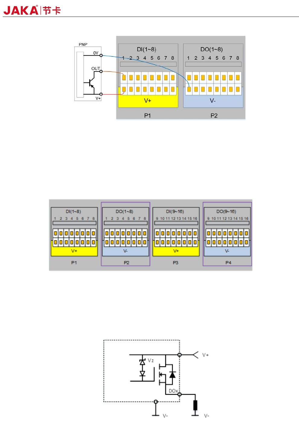
b) PNP type signal as input
JAKA Zu
3 v1.1 27
.
Figure 4-10
Figure 4-10 shows the input wiring diagram of the PNP interface. The V + pin is connected to V +, the
OUT pin is connected to DIx, and the 0V pin is connected to V-. When the signal is triggered, the LED on the
panel turns on, and the DIx status on the APP interface is changed.
4.3.3 Digital Output(DO)
Figure 4-11
The electric control cabinet has 16 channels PNP type output interface (DO1 ~ DO16) to support isolated
signal output.
The digital output uses a high-side output with a single continuous maximum current of 1A. However,
when V+ defaults to internal 24V power supply, the 24V power supply is limited to 1.5A. The typical internal
circuit diagram is as follows:
Figure 4-12
The typical block diagram is as follows: