20121120111955_KY8030_2_Maintenance_Manual_Eng_ver1.pdf - 第27页
Maintenance Manual | 27 1.2.3. L IMIT S EN SOR C HANGE Figure 1-4. X-Y Limit Sensor 1. Cut the power/the air s upply and press emergency switch. 2. Open the Front Door/Win dow and disassemble …

26 | KY-8030 2
3DSolderPasteInspectionSystem
Version 1.0
KOH YOUNG TECHNOLOGY INC.
5. DisassembleMotorBracketandCouplingfromX‐YFrame.
6. AfterinsertingCouplingtoScrewShaftandassembleMotorBracketandMotor.
7. FixScrewShaftMotorwithShaftfixingCouplingbolt.
ÚNote
yCheckiftheCouplingmovesbetweenScrewShaftandMotorShaftwithoutobstacleandfixwith
bolt.Ifthereisanyobstacle,disengagetheMotorfixingboltandsettheAlignoftheCoupling.
yChecktheboltstateafterassembly.
Maintenance Manual | 27
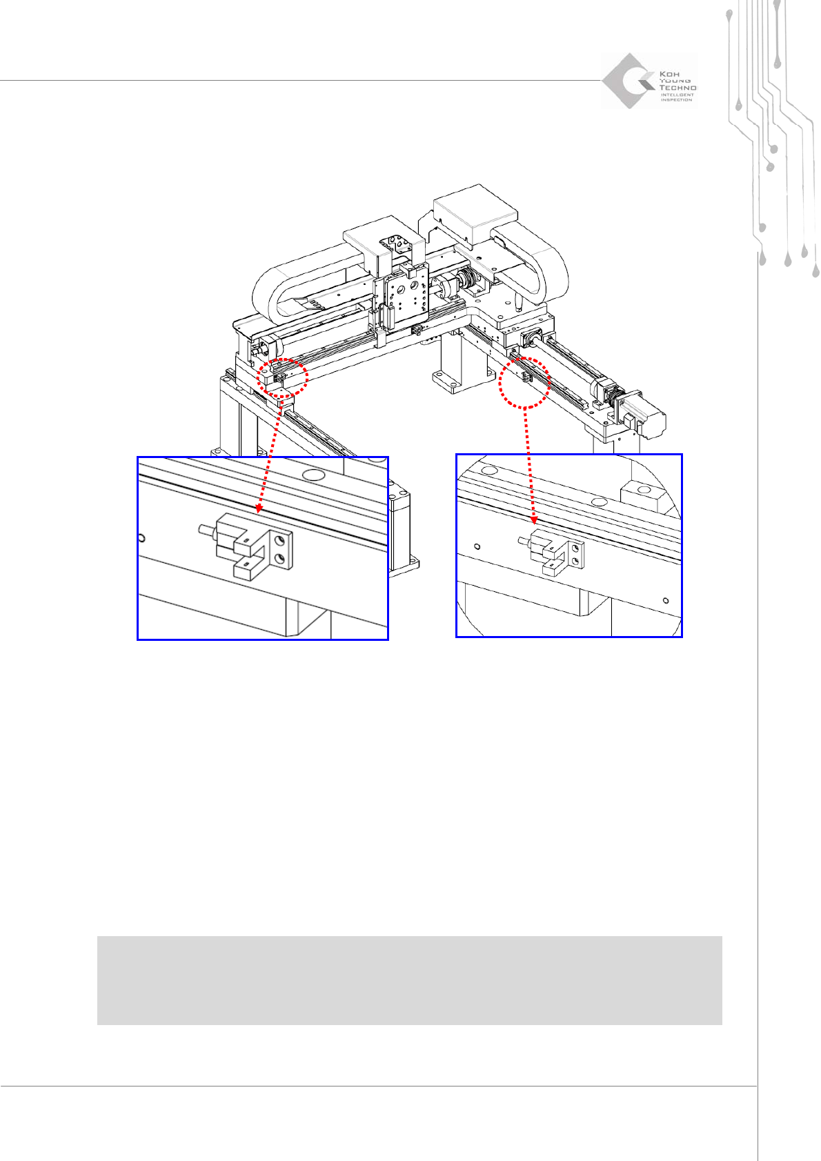
1.2.3. LIMIT SENSOR CHANGE
Figure 1-4. X-Y Limit Sensor
1. Cutthepower/theairsupplyandpressemergencyswitch.
2. OpentheFrontDoor/WindowanddisassembleRearCover/RightSideCover.
3. DisassembletheConnectorofchangingLimitSensor.
4. ChangetonewLimitSensor.
5. Combine theConnector of changed Limit Sensor and adjust the cable notto touch the
movingpartsofthesystem.
ÚNote
yManuallymovetheX‐YGantrytocheckanycontactwiththecable.
ySupplypowerandcheckiftheLimitSensorisproperlyoperatingbytheI/Oscreen.
28 | KY-8030 2
3DSolderPasteInspectionSystem
Version 1.0
KOH YOUNG TECHNOLOGY INC.
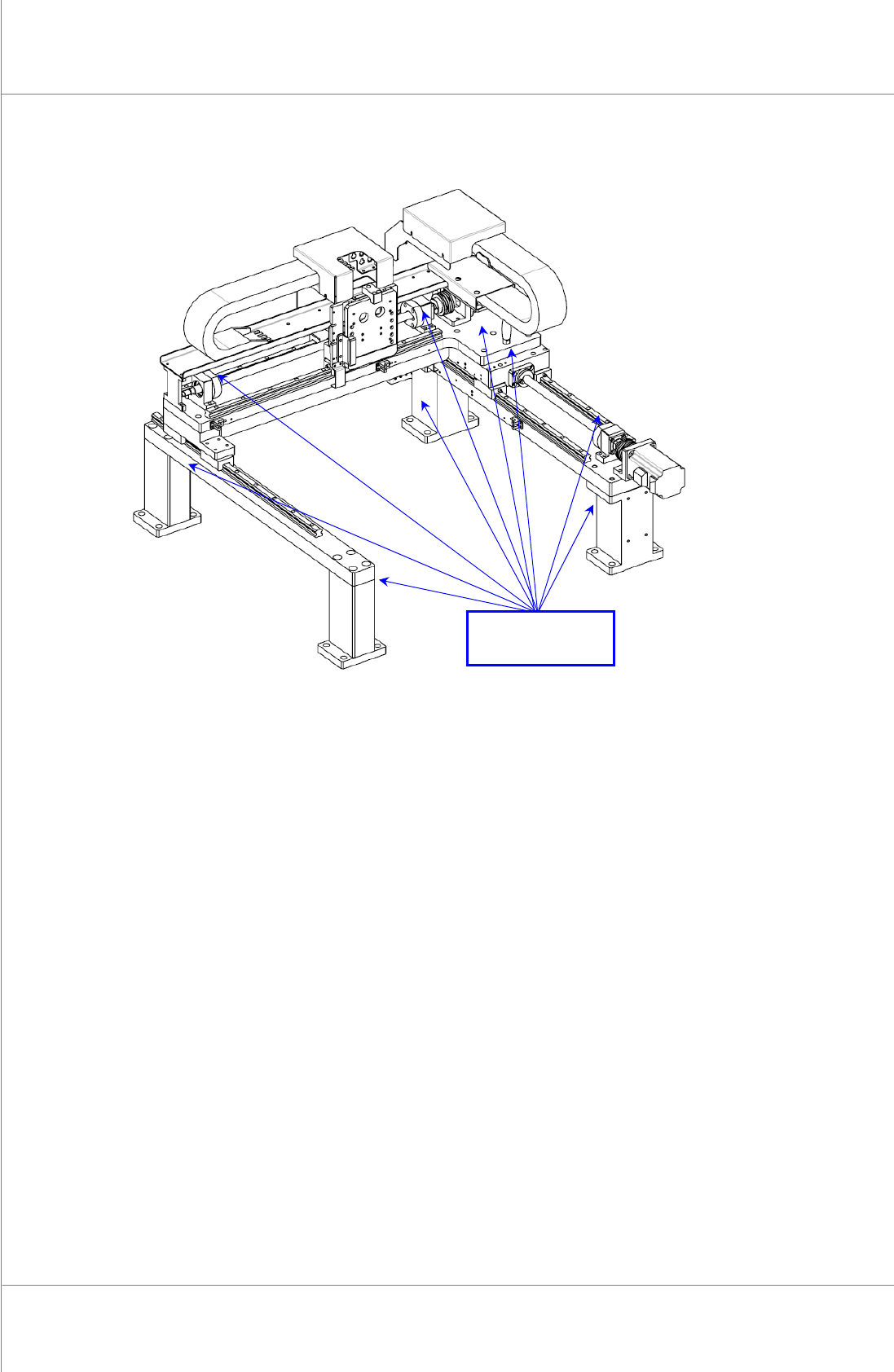
1.2.4. X-Y FRAME AND SUPPORT UNIT
Figure 1-5. X-Y Frame and Support Unit
1. Cutthepower/theairsupplyandpressemergencyswitch.
2. OpentheFrontDoor/WindowanddisassembleRearCover/RightSideCover.
3. Itisrecommendedtochecktheloosenboltsofabovewhengreasingevery6months
4. The abnormality of the positions above can result in the performance deterioration or
malfunction.
Checking
Positions