20121120111955_KY8030_2_Maintenance_Manual_Eng_ver1.pdf - 第63页
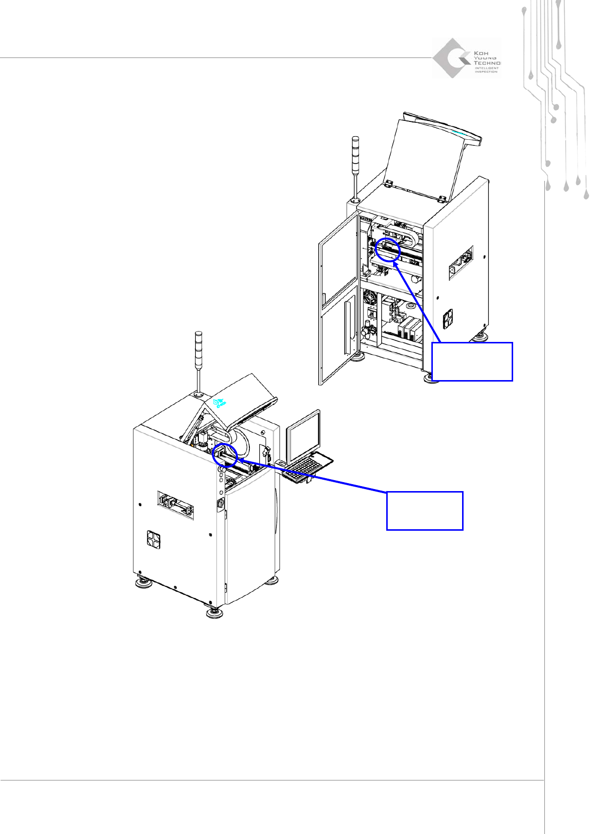
Maintenance Manual | 63 Figure 3-2. X-Y Axis Fix Bracket Disassemble the Axis Fix Bracket with wrench and check the X ‐ Y Gantry or Convey or for unnecessary items on them. X-Axis Fi…
62 | KY-8030 2
3DSolderPasteInspectionSystem
Version 1.0
KOH YOUNG TECHNOLOGY INC.
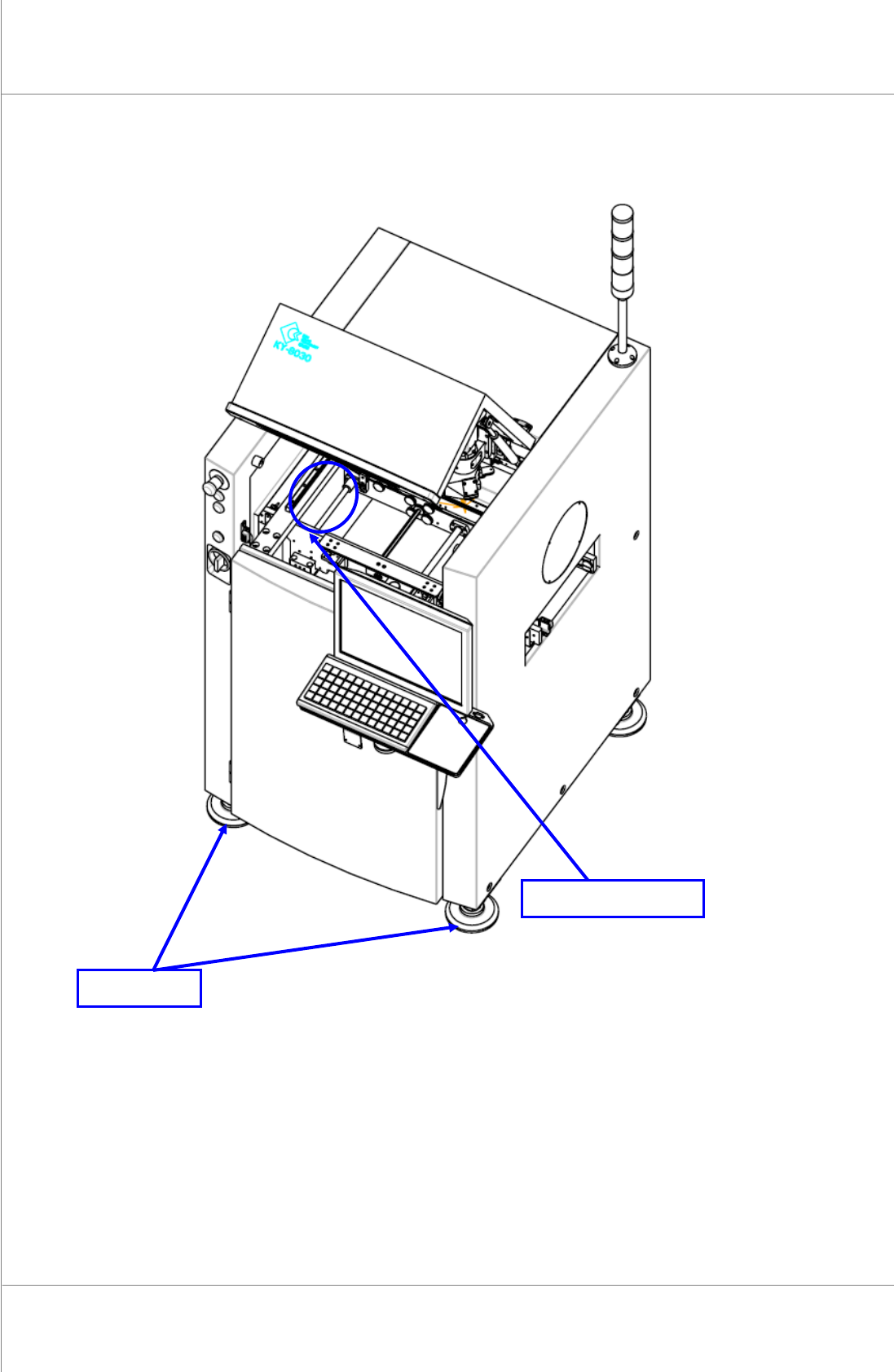
Figure 3-1. Cross Level Gauge and Foot Locations
Levelthesystembyadjustingthe4feetwithwrench.
Cross Level Gauge
Foot
Maintenance Manual | 63
Figure 3-2. X-Y Axis Fix Bracket
Disassemble the Axis Fix Bracket with wrench and check the X‐Y Gantry or Conveyor for
unnecessaryitemsonthem.
X-Axis
Fix Bracket
Y-Axis
Fix Bracket
64 | KY-8030 2
3DSolderPasteInspectionSystem
Version 1.0
KOH YOUNG TECHNOLOGY INC.
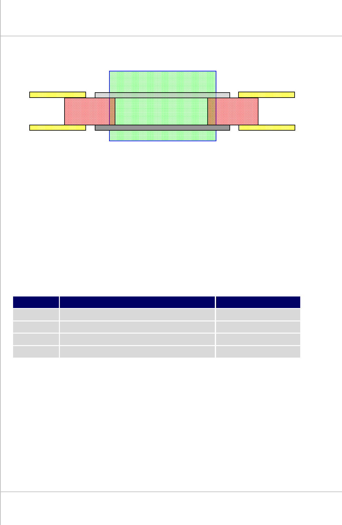
Figure 3-3. System Alignment
SetthesysteminalignmentwiththeFixRailsofthenextsystems.
CheckthePCBconveyingaftersettingthesystem.
3.2. Required Items for Installation
No.
Item
Unit
1
Cross Level Gauge
1
2
Wrench
1
3
Cart
1
4
PCB or Plate for System Alignment
2
KY-8030 2
Front Fix
Previous
System
Next
System
PCB or Plate PCB or Plate
Fix Rail
Moving Rail