20121120111955_KY8030_2_Maintenance_Manual_Eng_ver1.pdf - 第45页
Maintenance Manual | 45 1.2.14. A IR M ODULE Figure 1-15. Main Air Module Item Description Item Description 1 Fitting 4 S pace Bracket 2 Silencer 5 Filter Regulator 3 Air Release V alve 6 Pressure Sensor 1. Cut the p…

44 | KY-8030 2
3DSolderPasteInspectionSystem
Version 1.0
KOH YOUNG TECHNOLOGY INC.
10. Cleantheprojectionlenscover.
Note: Always check the contamination of lens cover before PCB inspection. The contamination can
causeperformancedeteriorationorerror.
Maintenance Manual | 45
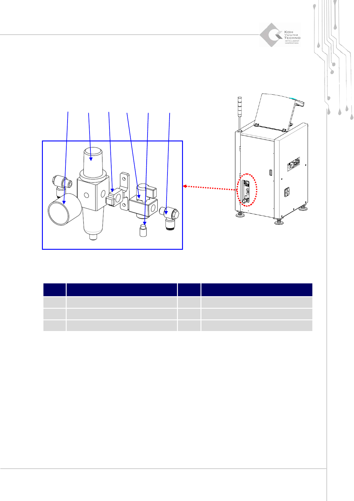
1.2.14. AIR MODULE
Figure 1-15. Main Air Module
Item Description Item Description
1 Fitting 4 Space Bracket
2 Silencer 5 Filter Regulator
3 Air Release Valve 6 Pressure Sensor
1. Cutthepower/theairsupplyandpressemergencyswitch.
2. OpentheFrontDoor/WindowanddisassembleRearCover/RightSideCover.
3. Disengage the bolt of Space Bracket and disassemble the Air Module (disassemble air‐
hosefirst).
4. AssemblenewAirModuleandconnectair‐hose.
5. Refertotheprior
pageforAirModuleSetting.
② ①④ ③ ⑤
⑥
46 | KY-8030 2
3DSolderPasteInspectionSystem
Version 1.0
KOH YOUNG TECHNOLOGY INC.
②
①
④
③
⑤
⑥
⑦ ⑧ ⑨
⑩
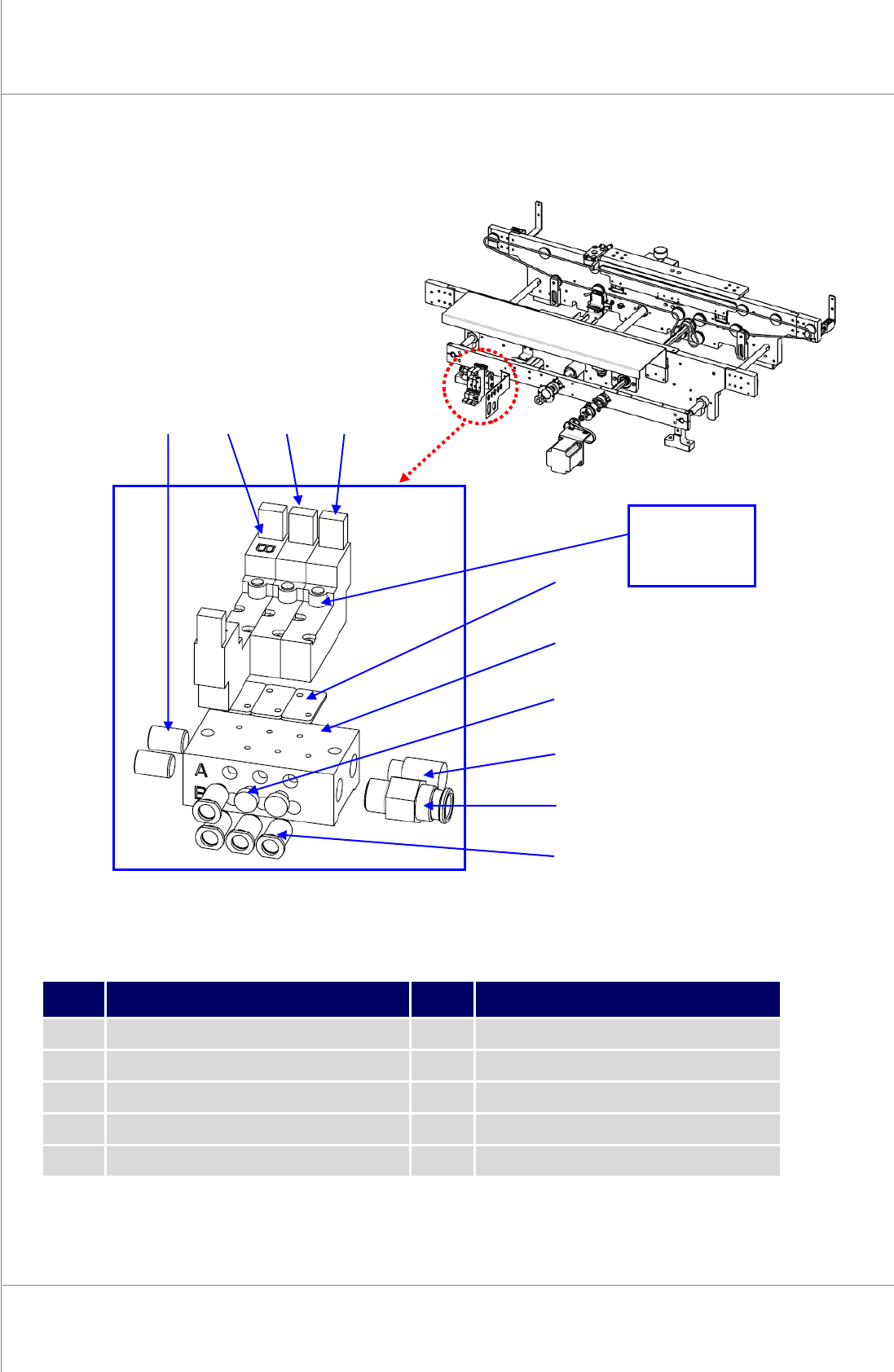
1.2.15. MANIFOLD COMPONENT AND SOLENOID VALVE CHANGE
Figure 1-16. Manifold
Item Description Item Description
1 Fitting 6 Solenoid Valve Pad
2 Fitting 7 Solenoid Valve
3 Silencer 8 Solenoid Valve
4 Fitting 9 Solenoid Valve
5 Manifold 10 Plug
1. Cutthepower/theairsupplyandpressemergencyswitch.
Manual
Operation
Switch