20121120111955_KY8030_2_Maintenance_Manual_Eng_ver1.pdf - 第64页
64 | KY -8030 2 3D Solder Paste Inspec tion System V ersion 1.0 K OH Y OUNG T ECHNOLOGY I NC . Figure 3-3. System Alignment Set the system in alignment with the Fix Rails of the next s…
Maintenance Manual | 63
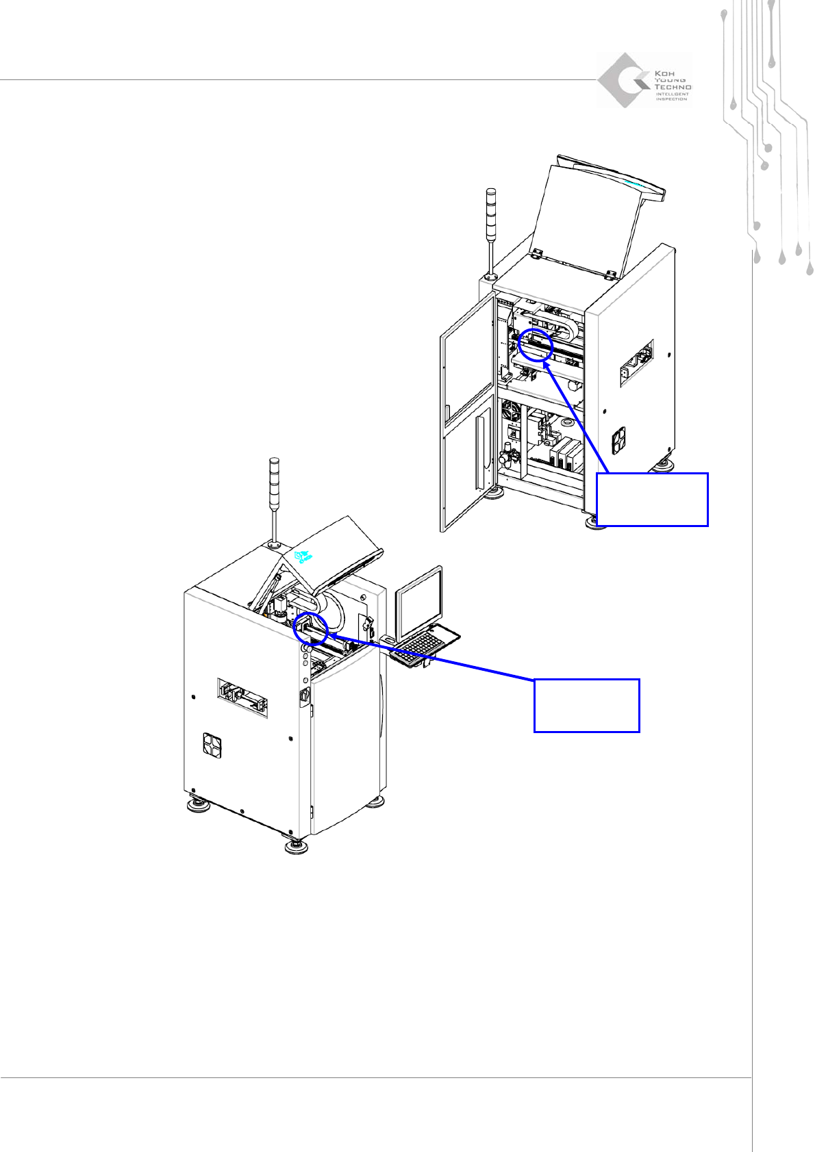
Figure 3-2. X-Y Axis Fix Bracket
Disassemble the Axis Fix Bracket with wrench and check the X‐Y Gantry or Conveyor for
unnecessaryitemsonthem.
X-Axis
Fix Bracket
Y-Axis
Fix Bracket
64 | KY-8030 2
3DSolderPasteInspectionSystem
Version 1.0
KOH YOUNG TECHNOLOGY INC.
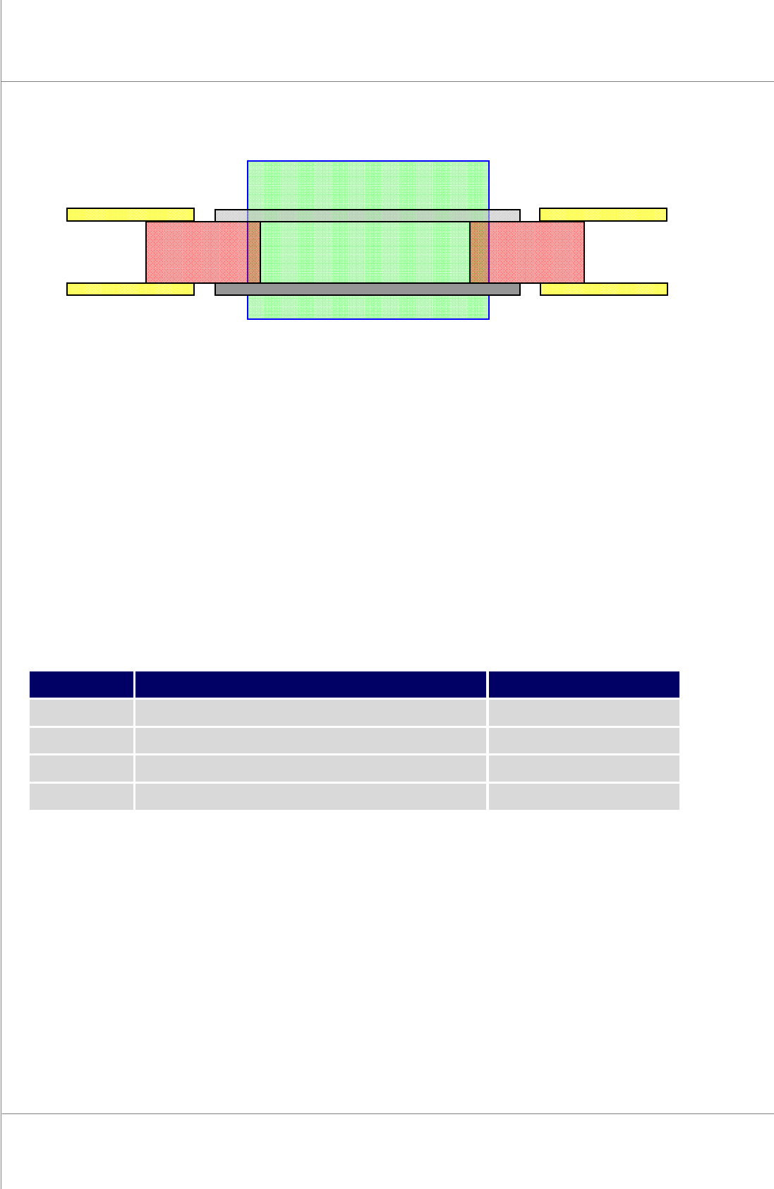
Figure 3-3. System Alignment
SetthesysteminalignmentwiththeFixRailsofthenextsystems.
CheckthePCBconveyingaftersettingthesystem.
3.2. Required Items for Installation
No.
Item
Unit
1
Cross Level Gauge
1
2
Wrench
1
3
Cart
1
4
PCB or Plate for System Alignment
2
KY-8030 2
Front Fix
Previous
System
Next
System
PCB or Plate PCB or Plate
Fix Rail
Moving Rail
Maintenance Manual | 65
3.3. Connecting 3 Phase Power
1. Ifyourpowersupplyprovidessingle‐phasevoltage,ensurethatthevoltagebetweenthe
U&Vphases(thevoltagebetweenleadAandB)isAC220VbeforeconnectingtheKY‐
80302system.
2. Or,ifitprovides3‐phasevoltage,useonlytwooftheU(lead
A),V(leadB)andW(lead
C) phases and ensure that the voltage between the two leads is AC 220V before
connectingtheKY‐80302system.Note:ThepossibleleadcombinationsareA&B,B&C
orC&A.
3. Check the voltage between A‐
F.G. (Field Ground) and B‐F.G. leads to see if it is
approximatelyAC100V.IfitisAC100V(adiscrepancyofAC10‐30Vcanoccur),connect
the F.G. lead provided to the F.G. lead of the system. This completes power cable
connection.
4. Unlikeinstep(3),if
theACvoltagebetweenA‐F.G.andB‐F.G.leadsis0(zero),itmaybe
thattheF.G.leadprovidedisfaulty.Shouldthisoccur,donotconnecttheF.G.leadtothe
systemandfollowthestepsfrom(5)instead.
5. Ifaproblemoccursasdescribedin
step(4),checktheACvoltagesbetweenleadAthat
willbewiredtothesystemandoneofthefeetofonemachine,andbetweenleadBthat
willbewiredtothesystemandoneofthefeetoftheothermachinetoseeiftheF.G.lead
provided
complies with the conditionstated instep(4),and thenfollowthestepsfrom
(6)
6. IfthefootoftheothermachineoffersanF.G.lead,connectittothesystem
7. Ifnot,donotconnectittothesystembutconsulttheadministrator.
8. In the case
of step (7), if static electricity or sparks tend to occur when a PCB in the
system or another machine istouched, thefootof the machine can be connected to the
systemalthoughitdoesnotofferanF.G.leadasdescribedinstep(3). Inthiscase,make
sure
to consult the administratorasthe systemcan be affected by powerfluctuationor
noise.