20121120111955_KY8030_2_Maintenance_Manual_Eng_ver1.pdf - 第40页
40 | KY -8030 2 3D Solder Paste Inspec tion System V ersion 1.0 K OH Y OUNG T ECHNOLOGY I NC . 5. Disassemble Buffer Ring Pulley1and Step Motor . 6. Assemble the new Step Motor in revers…
Maintenance Manual | 39
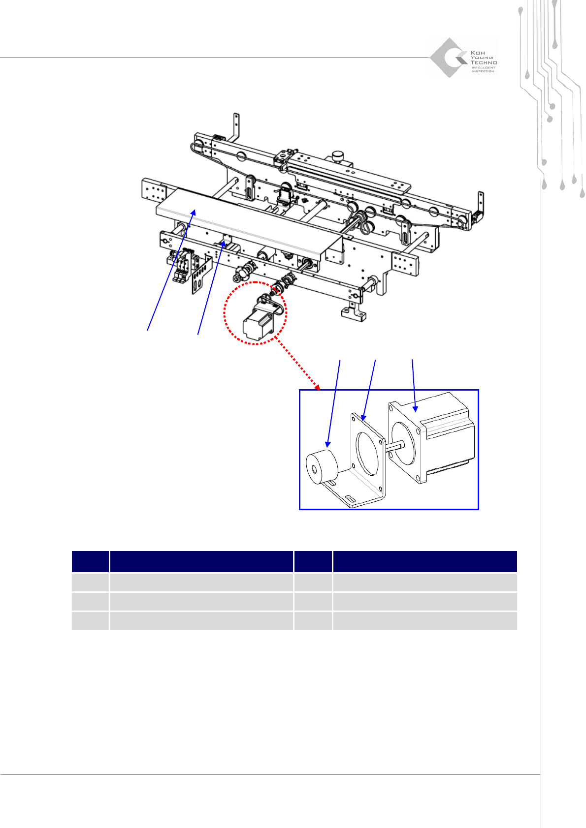
1.2.10. CONVEYOR RING BELT TRANSFER MOTOR
Figure 1-11. Ring Belt Transfer Motor
Item Description Item Description
1 Cable Motor Cover 4 Pulley Motor Bracket
2 Slide Bush Fix Bracket 5 Step Motor
3 Buffer Ring Pulley 1
1. Cutthepower/theairsupplyandpressemergencyswitch.
2. OpentheFrontDoor/WindowanddisassembleRearCover/RightSideCover.
3. DisassembleCableMotorCoverfromtheConveyor.
4. DisassemblePulleyMotorBracketfromSlideBushFixBracket.
②
①
④ ③ ⑤

40 | KY-8030 2
3DSolderPasteInspectionSystem
Version 1.0
KOH YOUNG TECHNOLOGY INC.
5. DisassembleBufferRingPulley1andStepMotor.
6. AssemblethenewStepMotorinreverseorderofthedisassembly.
7. SupplypowerandcheckiftheStepMotorisoperatingproperlyattheI/Oscreen.
Maintenance Manual | 41
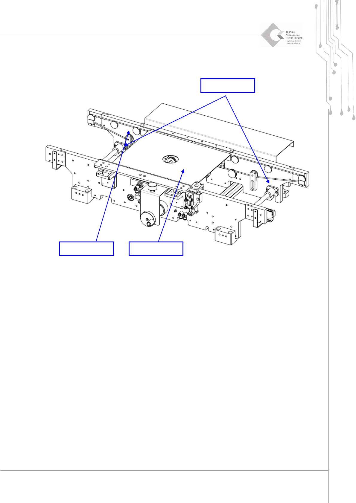
1.2.11. CONVEYOR WIDTH/RAIL SETTING
Figure 1-12. Conveyor Width Setting
1. Cutthepower/theairsupplyandpressemergencyswitch.
2. OpentheFrontDoor/WindowanddisassembleRearCover/RightSideCover.
3. DisengageboltstosettheSlideBushofMovingRail.
4. Insert PCB or Plate to Conveyor, move the Moving Rail to contact PCB or Plate to
MovingRail.
5. WhenPlatecontactsMovingRail,fixtheSlideBushwithbolts.
6. ConfirmthelengthoftheConveyorbycontrollingconveyormanually.
Moving Rail PCB or Plate
Slide Bush