20121120111955_KY8030_2_Maintenance_Manual_Eng_ver1.pdf - 第62页
62 | KY -8030 2 3D Solder Paste Inspec tion System V ersion 1.0 K OH Y OUNG T ECHNOLOGY I NC . Figure 3-1. Cross Level Gauge and Foot Loca tions Level the system by adjusting the 4 feet with w…
Maintenance Manual | 61
3. SYSTEM INSTALLATION
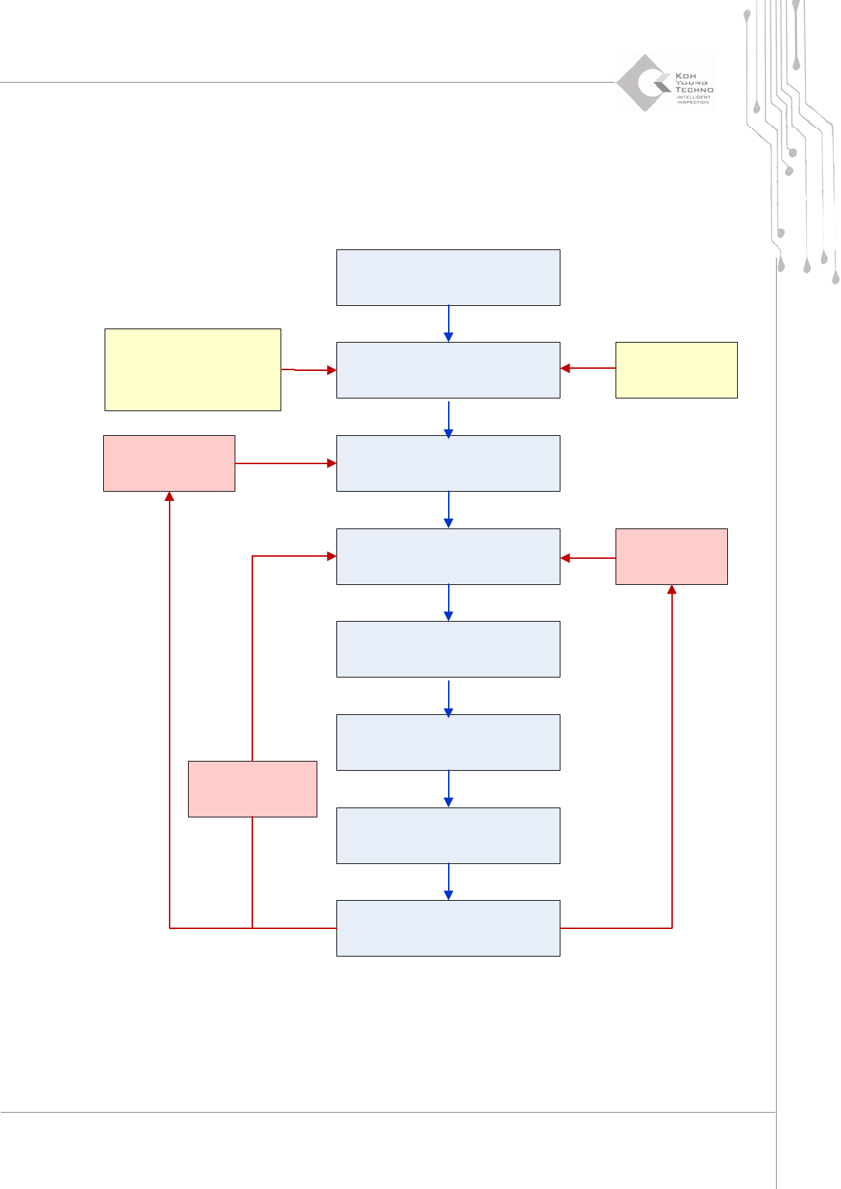
3.1. System Installation Flow Chart
System, PC, Monitor Unpacking
Open the front door/back cover
and connect the power cable
with the PC
Install the system in the Line and
connect SMEMA
X-Y Gantry and I/O TEST at the
GUI using manual
Power/Air supply
System Align and leveling
(refer to the diagram)
Disassemble the X-Y Gantry fix
Bracket
(refer to the diagram)
Operate the system if no
abnormality occurs
PCB import/export
conveying failure
PCB conveying
failure
Vibration when
operating the
system
Refer to the power
connection part for the
connection of 3phase
voltage
Label check
when connecting
the cable
62 | KY-8030 2
3DSolderPasteInspectionSystem
Version 1.0
KOH YOUNG TECHNOLOGY INC.
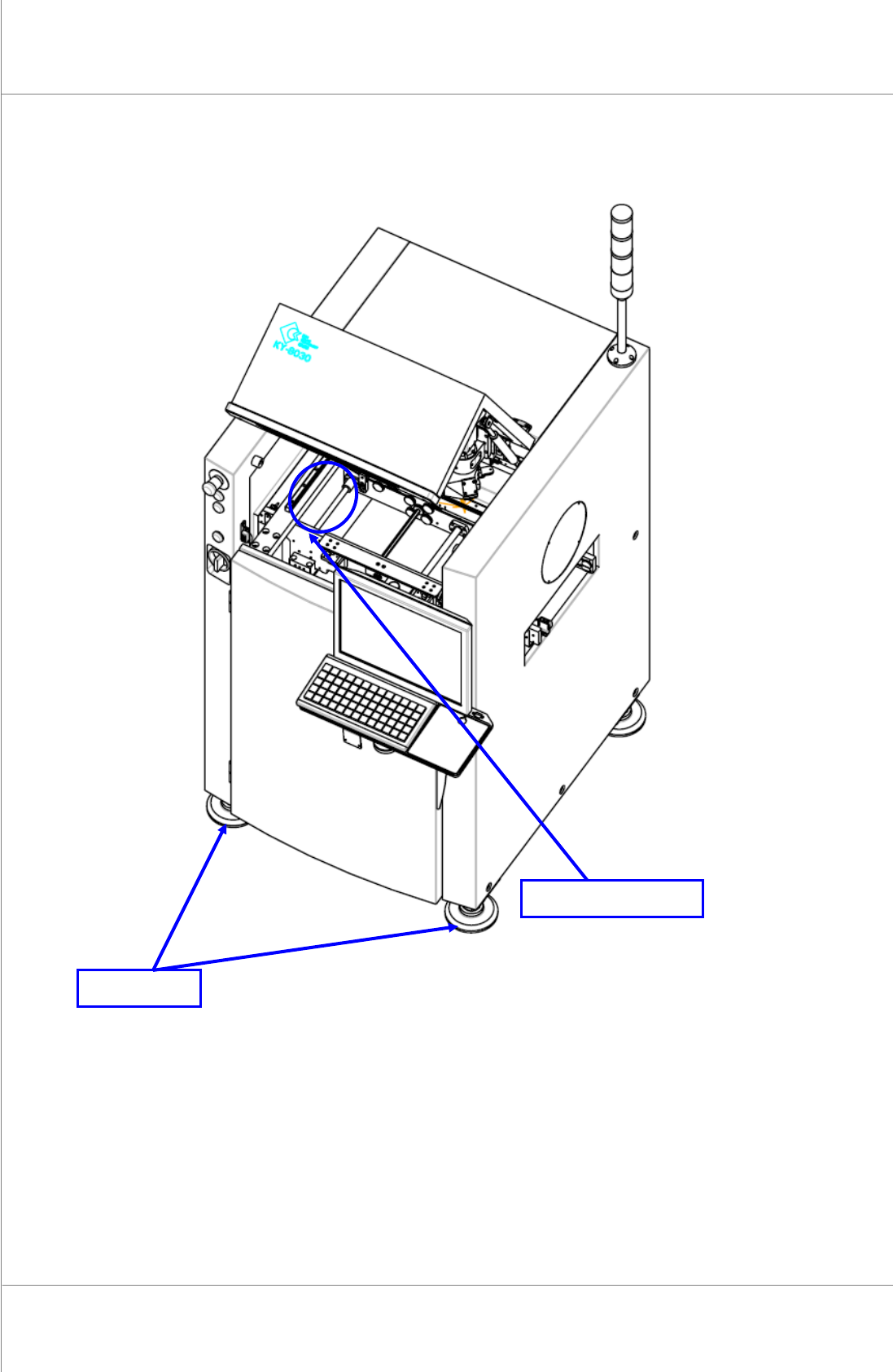
Figure 3-1. Cross Level Gauge and Foot Locations
Levelthesystembyadjustingthe4feetwithwrench.
Cross Level Gauge
Foot
Maintenance Manual | 63
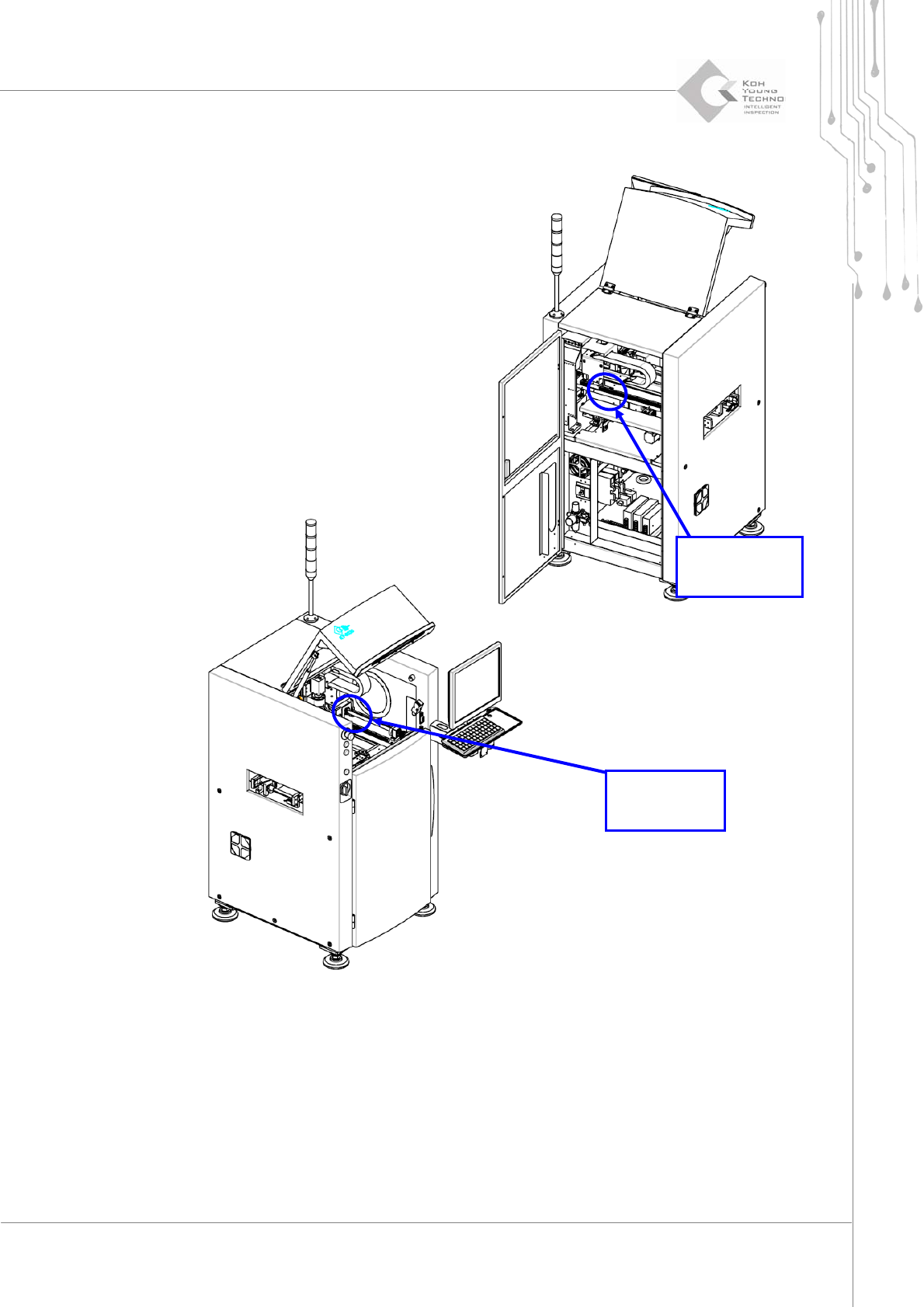
Figure 3-2. X-Y Axis Fix Bracket
Disassemble the Axis Fix Bracket with wrench and check the X‐Y Gantry or Conveyor for
unnecessaryitemsonthem.
X-Axis
Fix Bracket
Y-Axis
Fix Bracket