20121120111955_KY8030_2_Maintenance_Manual_Eng_ver1.pdf - 第41页
Maintenance Manual | 41 1.2.11. C ONVEYOR W IDTH /R AIL S ETTIN G Figure 1-12. Conveyor Wid th Setting 1. Cut the power/the air supply and press emergency switch. 2. Open the Front Door/Window a…

40 | KY-8030 2
3DSolderPasteInspectionSystem
Version 1.0
KOH YOUNG TECHNOLOGY INC.
5. DisassembleBufferRingPulley1andStepMotor.
6. AssemblethenewStepMotorinreverseorderofthedisassembly.
7. SupplypowerandcheckiftheStepMotorisoperatingproperlyattheI/Oscreen.
Maintenance Manual | 41
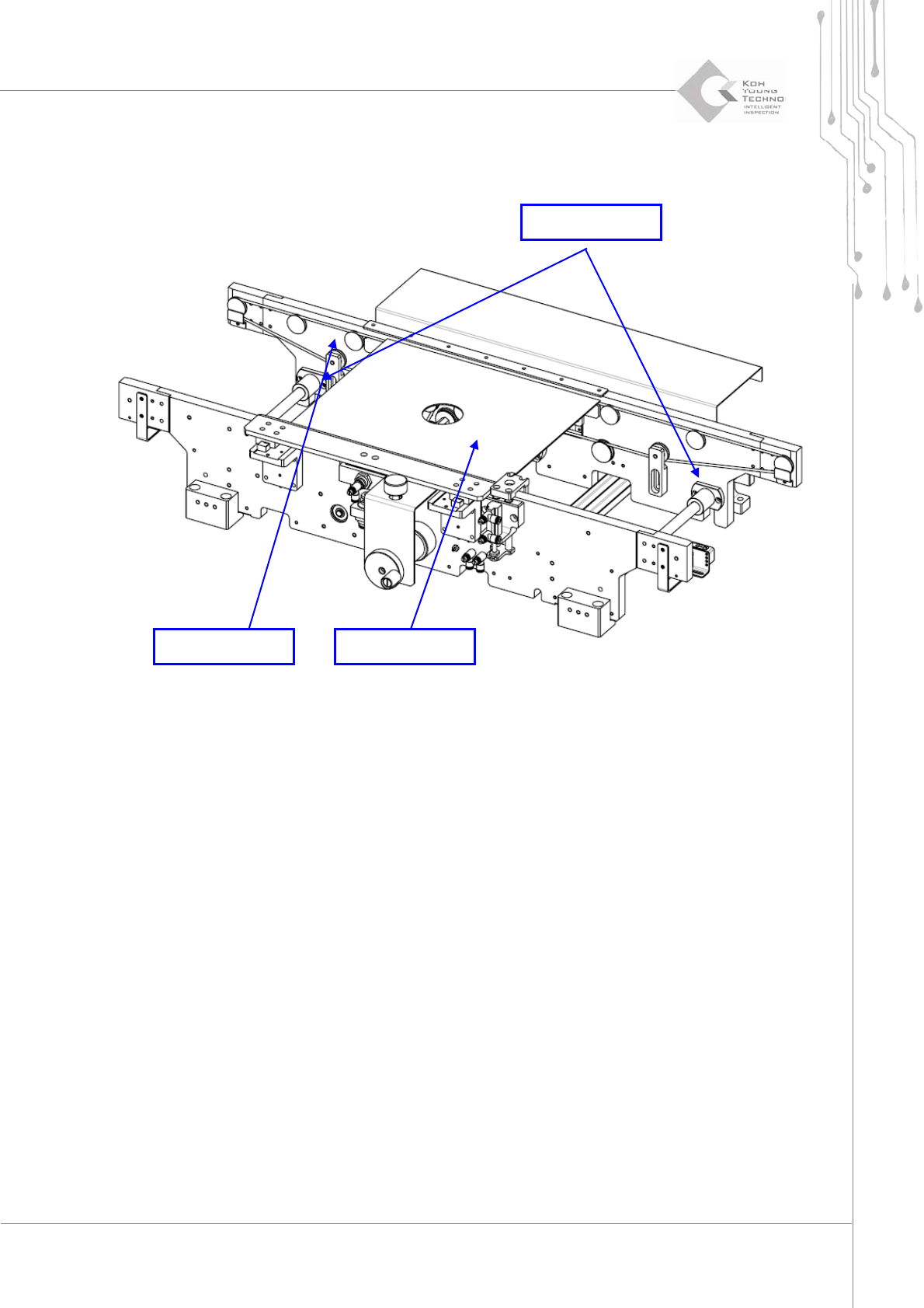
1.2.11. CONVEYOR WIDTH/RAIL SETTING
Figure 1-12. Conveyor Width Setting
1. Cutthepower/theairsupplyandpressemergencyswitch.
2. OpentheFrontDoor/WindowanddisassembleRearCover/RightSideCover.
3. DisengageboltstosettheSlideBushofMovingRail.
4. Insert PCB or Plate to Conveyor, move the Moving Rail to contact PCB or Plate to
MovingRail.
5. WhenPlatecontactsMovingRail,fixtheSlideBushwithbolts.
6. ConfirmthelengthoftheConveyorbycontrollingconveyormanually.
Moving Rail PCB or Plate
Slide Bush
42 | KY-8030 2
3DSolderPasteInspectionSystem
Version 1.0
KOH YOUNG TECHNOLOGY INC.
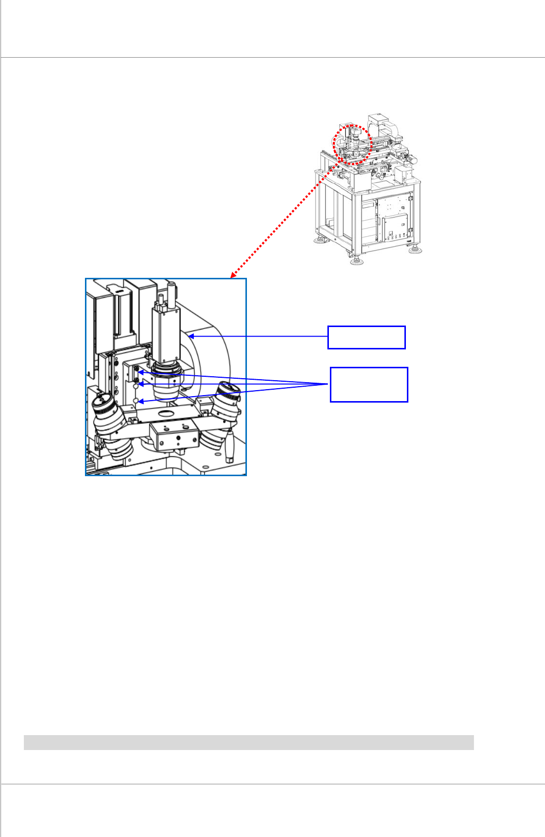
1.2.12. PROBE CHANGE
Figure 1-13. Probe Change
1. Cutthepower/theairsupplyandpressemergencyswitch.
2. Openthe FrontDoor/WindowanddisassembleRearCover/RightSideCover.
3. DisassembleProbeUnitfromX‐Axis(eliminateConnector)
4. AssemblenewProbeUnittoX‐Axis(connecttheConnector)
5. SupplypowerandcheckiftheilluminationandPZT
isoperatingproperlyatthemanual
mode.
6. ExecuteCalibrationoftheProbe(refertoProbeCalibrationmanualforthis)
Note:PZTAmpshouldbechangedwhenchangingProbe.
Probe Fixing
Position
Probe