20121120111955_KY8030_2_Maintenance_Manual_Eng_ver1.pdf - 第36页
36 | KY -8030 2 3D Solder Paste Inspec tion System V ersion 1.0 K OH Y OUNG T ECHNOLOGY I NC . Connector . 4. Assemble new Up/Down Limit Sensor to Fix Rail and assemble Connector checkin…
Maintenance Manual | 35
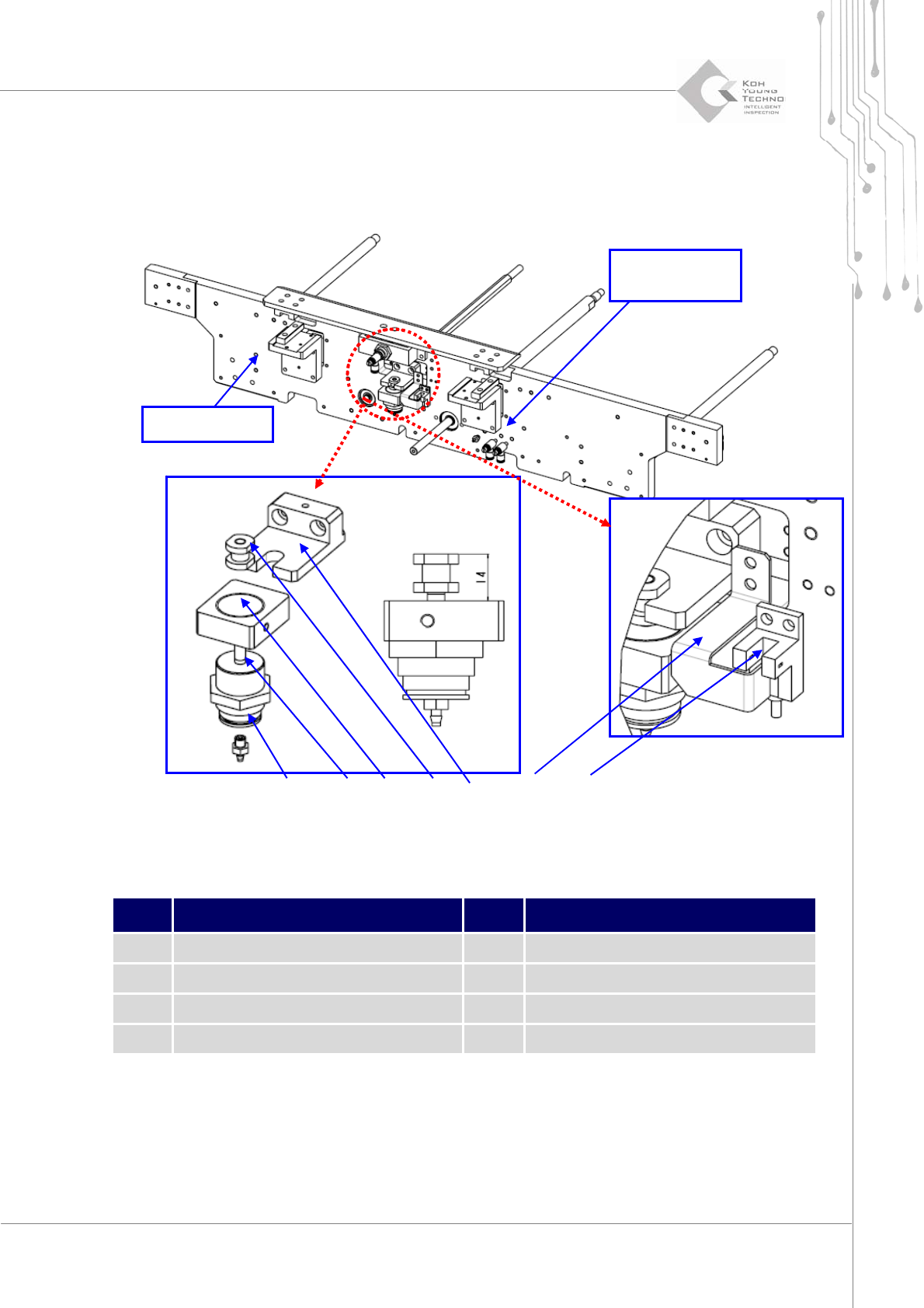
1.2.8. PCB CLAMPING CYLINDER AND UP/DOWN LIMIT SENSOR CHANGE
Figure 1-9. PCB Clamping Cylinder and Up Sensor
Item Description Item Description
1 Up/Down Limit Sensor 5 Up/Down Cylinder Bracket
2 Up/Down Dog 6 Up/Down Cylinder
3 Rail Fix Bracket 7 Fitting
4 Up/Down Cylinder Joint
1. Cutthepower/theairsupplyandpressemergencyswitch.
2. OpentheFrontDoor/WindowanddisassembleRearCover/RightSideCover.
3. Disassemble Fix Rail from Up/Down Dog and disassemble Up/Down Limit Sensor
Fixed Rail
Speed
Controller
①
②
③
④
⑤⑥ ⑦

36 | KY-8030 2
3DSolderPasteInspectionSystem
Version 1.0
KOH YOUNG TECHNOLOGY INC.
Connector.
4. AssemblenewUp/DownLimitSensortoFixRailandassembleConnectorcheckingI/O
Number.
5. Disassemble Rail Fix Bracket from Fix Rail and disassemble Up/Down Cylinder from
Up/DownCylinderBracket.(first,eliminateair‐hosefromFitting)
6. DisassembleUp/DownCylinderJointfromUp/DownCylinder.
7. AssemblenewUp/DownCylinderin
reverseorderofdisassembly.
8. Supply power and check if the Up/Down Cylinder and Up/Down Limit Sensor is
operatingproperlyattheI/Oscreen.
ÚNote:
Up/DownCylinderandUp/DownCylinderJointshouldbeassembledasthesizeofdiagram.
SensorCableshouldnotinterferewhenUp/DownCylinderisoperating.
SettheUp/DownCylinderspeedbytheSpeedControllerindicatedinthediagram.
Maintenance Manual | 37
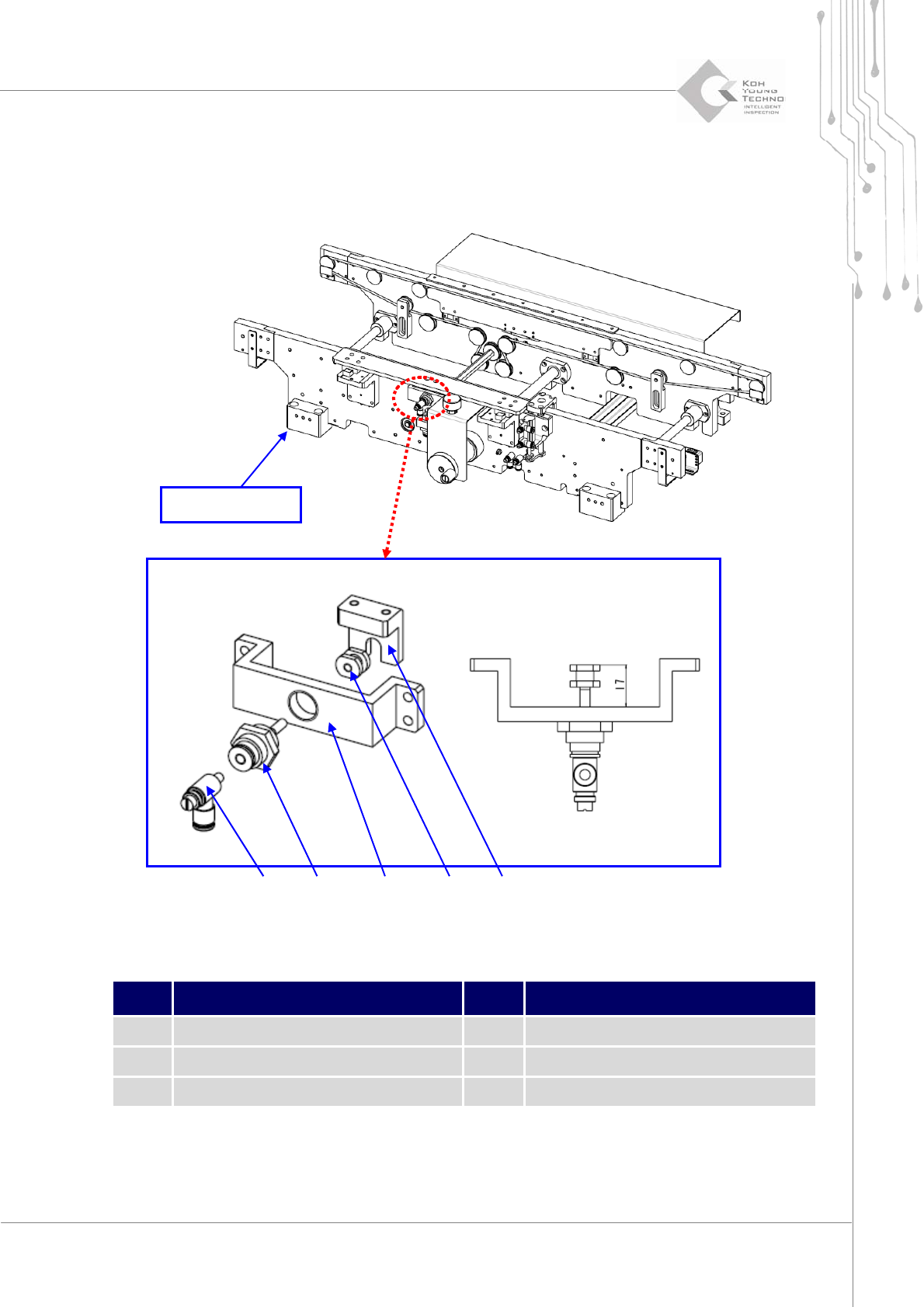
1.2.9. CONVEYOR HEIGHT GUIDE
Figure 1-10. Height Guide
Item Description Item Description
1 Spring 4 Height Guide Cylinder
2 Cylinder Shaft Joint 5 Speed Controller
3 Height Joint Bracket
1. Cutthepower/theairsupplyandpressemergencyswitch.
② ①
④
③
⑤
Fixed Rail