BA-UI-EN-D33363.pdf - 第13页
D33363 | Date 01/2020 13 Construction and description 2.6 Connections and interfaces 2.6.1 Electrical connection This appliance is intended for operation on an electrical power system with a system imped- ance Z max of a…
12 D33363 | Date 01/2020
Construction and description
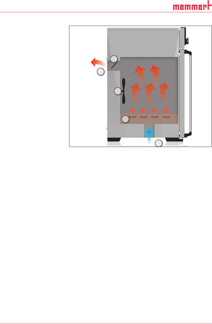
2.3 Function
Appliances of the UN... and
IN
... type series feature
natural circulation (convec-
tion). For the UF
... and IF...
type series, air is circulated
by a fan at the working
chamber rear panel Fig. 3 ,
No. 1). It increases the air
flow and provides stronger
horizontal forced air
circulation than natural
convection.
In both the convection and
fan ventilated appliances,
supply air (2) is preheated
in a pre-heating chamber
(3). Through the ventilation
slits in the side panel of the
working chamber, the pre-
heated air is introduced into
the interior of the chamber.
The supply and exhaust air
(5) volume (air change) is
controlled by the air flap
(4) on the rear panel of the
appliance.
2.4 Material
For the outer housing, MEMMERT deploys stainless steel (Mat.No. 1.4016 – ASTM 430) and
for the interior, stainless steel (Mat.No. 1.4301 – ASTM 304) is used, which stands out through
its high stability, optimal hygienic properties and corrosion-resistance towards many (but not
all!) chemical compounds (caution for example with chlorine compounds).
The chamber load for the appliance must be carefully checked for chemical compatibility with
the materials mentioned. A material resistance table can be requested from the manufacturer.
2.5 Electrical equipment
► Operating voltage and current consumption: See nameplate
► Protection class I, i.e. operating insulation with PE conductor in accordance with EN 61010
► Protection type IP 20 acc. to EN 60 529
► Interference suppression acc. to EN 55011 class B
► Appliance fuse: Fusible link 250 V/15 A quick-blow
► The temperature controller is protected with a miniature fuse 100 mA (160 mA at 115 V)
4
1
2
5
3
Fig. 3 Function
1 Fan
2 Fresh air
3 Pre-heating chamber
4 Air flap
5 Exhaust air
D33363 | Date 01/2020 13
Construction and description
2.6 Connections and interfaces
2.6.1 Electrical connection
This appliance is intended for operation on an electrical power system with a system imped-
ance Z
max
of a maximum of 0.292 ohm at the point of transfer (service line). The operator
must ensure that the appliance is operated only on an electrical power system that meets
these requirements. If necessary, you can ask your local energy supply company what the
system impedance is.
Observe the country-specific regulations when connecting (e.g. in Germany
DIN VDE 0100 with residual current circuit breaker).
2.6.2 Communication interface
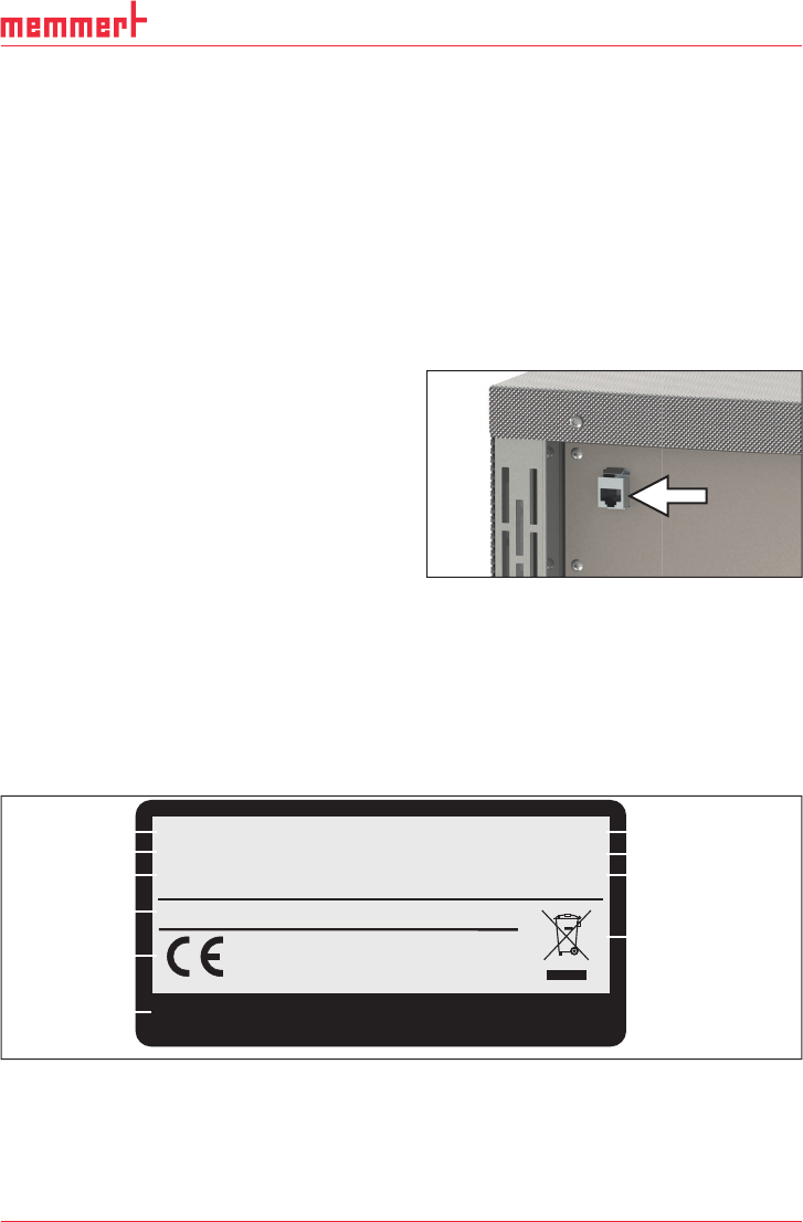
The Ethernet interface is intended for appliances which meet the requirements of IEC 60950-1.
Via Ethernet interface, the appliance can be
connected to a network to read out protocol
logs with AtmoCONTROL, the optional
appliance software. The Ethernet interface is
located on the rear of the appliance (Fig. 4 ).
For identification purposes, each appliance
connected must have its own unique IP ad-
dress. Setting the IP address is described on
page 38.
With an optional USB to Ethernet converter,
the appliance can be directly connected to a
computer / laptop (see Optional accessories
on page 16).
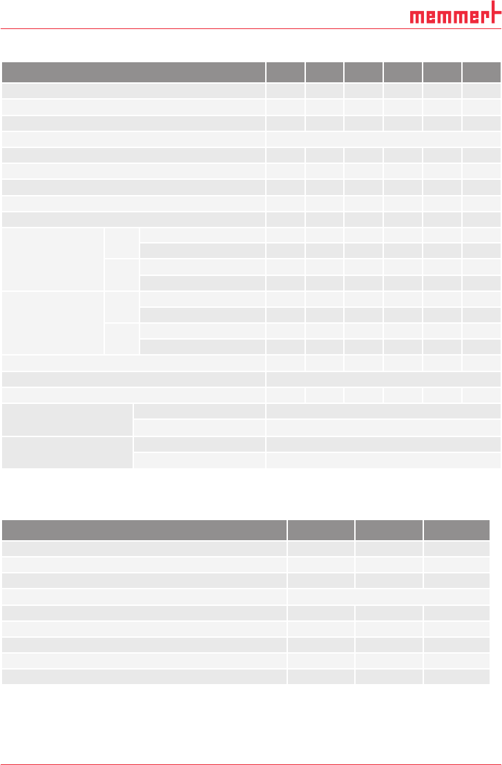
2.7 Designation (nameplate)
The nameplate (Fig. 5) provides information about the appliance model, manufacturer and
technical data. It is attached to the front of the appliance, on the right side under the door
(see page 10).
GmbH+Co.KG D-91126 Schwabach FRG
Äußere
Rittersbacher Str. 38 Made in Germany
Schutzart DIN EN 60529 - IP 20
1
2
3
4
5
6
10
9
8
7
Typ: UN260
230 V~ 50/60 Hz
DIN12880-2007-Kl.: 1
F-Nr.: B618.3008
14,8 A 3400 W
Nenntemp.: 300 °C
Fig. 5 Nameplate (example)
1 Type designation
2 Operating voltage
3 Applied standard
4 Protection type
5 CE conformity
6 Address of manufacturer
7 Disposal note
8 Temperature range
9 Connection / power ratings
10 Appliance number
Fig. 4 Ethernet interface
14 D33363 | Date 01/2020
Construction and description
2.8 Technical data
Appliance size 30 55 75 110 160 260
Appliance width D
1
[mm] 585 585 585 745 745 824
Appliance height E
1
[mm] 707 787 947 867 1107 1186
Appliance depth F
1
(footprint) [mm] 434 514 514 584 584 684
Depth of door lock [mm] 56
Working chamber width A
1
[mm] 400 400 400 560 560 640
Working chamber height B
1
[mm] 320 400 560 480 720 800
Working chamber depth C
1
[mm] 250 330 330 400 400 500
Chamber volume [litres] 32 53 74 108 161 256
Weight [kg] 48 57 66 78 96 110
Power [W]
I...
115 V, 50/60 Hz 800 900 900 900 900 900
230 V, 50/60 Hz 1600 1000 1250 1400 1600 1700
U...
230 V, 50/60 Hz 1600 2000 2500 2800 3200 3400
115 V, 50/60 Hz 1600 1700 1800 1800 1800 1800
Current
consumption [A]
I...
230 V, 50/60 Hz 7,0 4,3 5,4 6,1 7,0 7,4
115 V, 50/60 Hz 7,0 7,8 7,8 7,8 7,8 7,8
U...
230 V, 50/60 Hz 7,0 8,7 10,9 12,2 13,9 14,8
115 V, 50/60 Hz 13,9 14,8 15,6 15,6 15,6 15,6
max. number of sliding shelves 3 4 6 5 8 9
max. load per sliding shelve [kg] 20
max. load per appliance [kg] 60 80 120 175 210 300
Setting temperature range
IN/IF +20 bis +80 °C
2
UN/UF +20 bis +300 °C
2 3
Adjustment precision
IN/IF 0,1 K
UN/UF bis 99,9 °C: 0,1 K, ab 100 °C: 0,5 K
1
See Fig. 6 on page 15
2
With the interior lighting on, the minimum temperature might not be reached.
3
to +250 °C if your device is equipped with a glass door
Appliance size 450 750 1060
Appliance width D
1
[mm] 1224 1224 1224
Appliance height E
1
[mm] 1247 1720 1720
Appliance depth F
1
(footprint) [mm] 784 784 1035
Depth of door lock [mm] 56
Working chamber width A
1
[mm] 1040 1040 1040
Working chamber height B
1
[mm] 720 1200 1200
Working chamber depth C
1
[mm] 600 600 850
Chamber volume [litres] 449 749 1060
Weight [kg] 170 217 252