BA-UI-EN-D33363.pdf - 第22页
22 D33363 | Date 01/2020 Delivery , tr ansport and setting up 3.6.4 Adjusting the doors For appliances it is possible to adjust doors that warp due to the floor conditions. In order to do so, every door has two adjuster …
D33363 | Date 01/2020 21
Delivery, transport and setting up
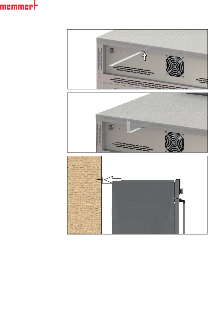
3.6.3 Tilt protection
Attach the appliance to a
wall with the tilt protection.
The tilt protection is included
in the delivery.
1. As illustrated, fasten the
tilt protection to the rear
side of the appliance.
2. Bend the tilt protec-
tion upwards by 90 ° in
the desired distance to
the wall (consider the
minimum distance to the
wall, see Fig. 8).
3. Drill a hole, insert a plug
and screw the tilt protec-
tion to a suitable wall.
22 D33363 | Date 01/2020
Delivery, transport and setting up
3.6.4 Adjusting the doors
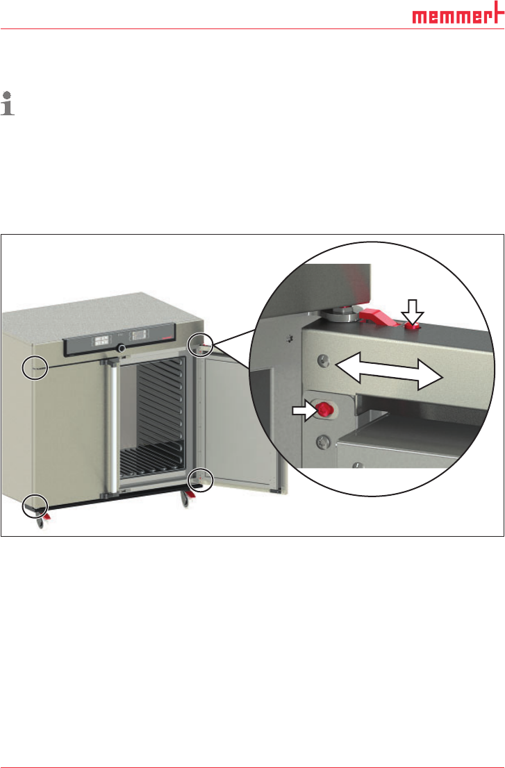
For appliances it is possible to adjust doors that warp due to the floor conditions. In order to
do so, every door has two adjuster screws at the top and at the bottom (Fig. 9).
First, adjust the door at the top and then, if further adjustment is necessary, at the bottom
as well.
1. Open the door.
2. Undo the screws.
3. Adjust the door.
4. Tighten the screws again.
5. Check door alignment.
6. If necessary, readjust.
Fig. 9 Door adjustment screws
D33363 | Date 01/2020 23
Putting into operation
4. Putting into operation
Caution:
The first time the appliance is operated, it must not be left unattended until it has reached
the steady state.
4.1 Connecting the appliance
WARNING
Condensation might cause a short circuit. After transport or storage
at high humidity conditions, the appliance shall be stored unpacked
at normal conditions for at least 24 hours. During this period of time
the appliance shall not be connected to the power supply.
Caution:
Observe the country-specific regulations when making connections (e.g. in Germany DIN
VDE 0100 with residual current circuit breaker). Observe the connection and power rat-
ings (see nameplate and Technical data on page 14). Make sure to establish a safe PE
conductor connection.
Lay the power cable so that
► it is always accessible and within reach so it can be disconnected quickly in the event of
failure or emergencies;
► no one can trip over it;
► it does not come into contact with any hot parts.
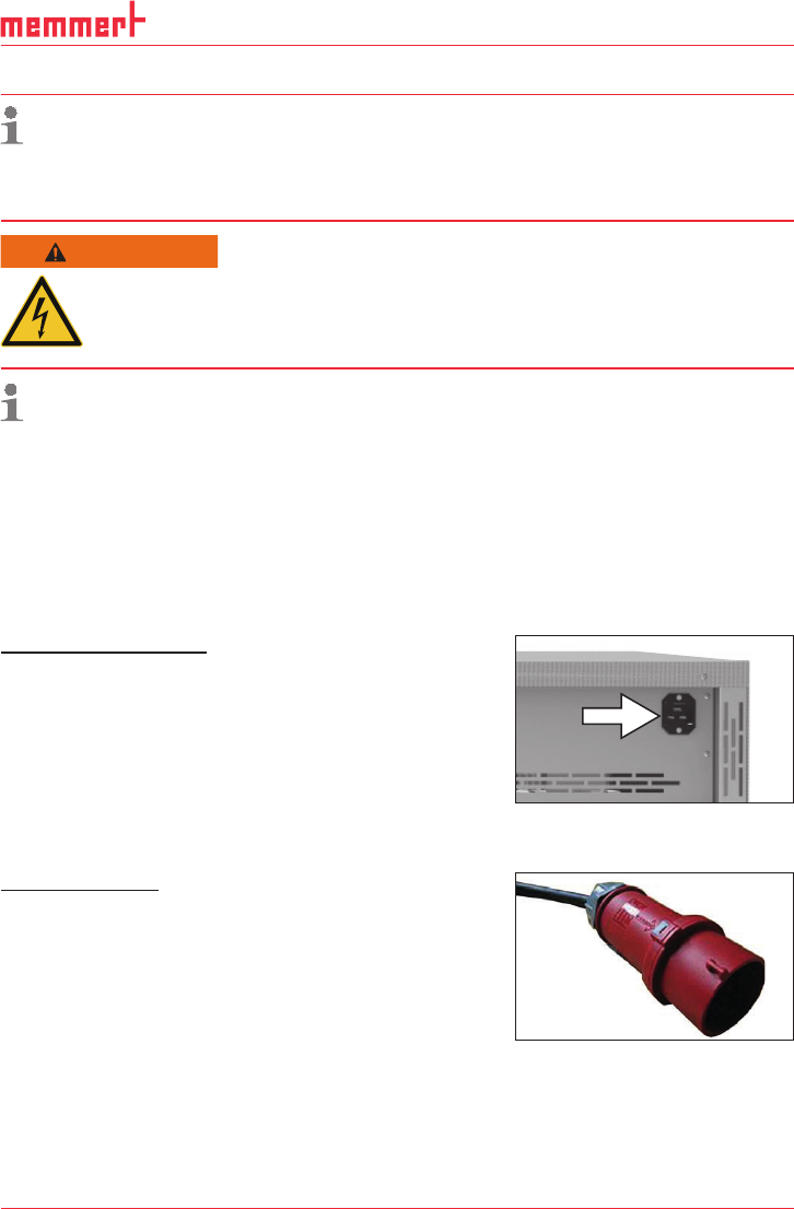
230/115-V appliances:
Plug the provided power cable into the rear of the appli-
ance and connect it to a CEE 7/4 socket (Fig. 10).
400V appliances:
The power cable is permanently installed. Connect the
plug to a 400 V CEE coupling (Fig. 11).
Fig. 10 Power connection
230/115 V
Fig. 11 400 V CEE connection