BA-UI-EN-D33363.pdf - 第30页
30 D33363 | Date 01/2020 Operation and control 3. Press the confirmation key . The display now shows the remaining time in a large font and the approximate end time in a smaller font beneath. TIMER 30 m 04 h End 13:30 23…
D33363 | Date 01/2020 29
Operation and control
5.4.4 Manual mode
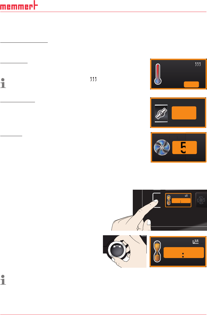
In this operating mode, the appliance runs in permanent operation at the values set on the
ControlCOCKPIT.
Adjustment options
As described in chapter 5.4.2, you can set the following parameters after pressing the cor-
responding activation key (in any sequence):
Temperature
Adjustment range: model dependent (see nameplate and technical
date on page 14)
Heating operation is indicated by the
symbol.
You can select °C or °F as the temperature unit displayed (see
page 39).
24.4 °C
TEMP
180.4 °CSet
Air flap position
Adjustment range: 0 % (closed, recirculating operation) to 100 %
(completely opened, fresh air operation) in steps of 10%
FLAP
%40
Fan speed
(only for UF
.../IF... appliances)
Adjustment range: 0 to 100 % in steps of 10%
FAN
%
50
FAN
A
5.4.5 Operation with digital backwards counter with target time setting,
adjustable from 1 minute to 99 days (Timer)
In timer operation, you can adjust the time the appliance runs at the set value.
1. Press the activation key to the left of
the timer display. The timer display is
activated.
FA
FA
TIMER
-
Ende
9:00 23.11.
--h- m
2. Turn the turn control until the desired
duration is displayed – in this example 4
hours 30 minutes. The approximate end
time is shown beneath, in a smaller font.
TIMER
End
0
13:30 23.11.
04 mh 3
Up to a duration of 23 hours 59 minutes, the time is displayed in hh:mm (hours:minutes)
format. For 24 hours and more, the format dd:hh (days:hours) is used. The maximum
duration adjustable is 99 days 00 hours.
30 D33363 | Date 01/2020
Operation and control
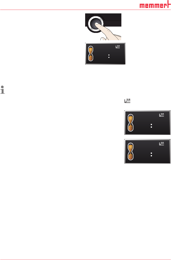
3. Press the confirmation key.
The display now shows the remaining time in
a large font and the approximate end time in
a smaller font beneath.
TIMER
30m04h
End
13:30 23.11.
4. Now, as described under 5.4.2, set the individual values for temperature, air flap position
etc. which you want the appliance to operate at. The set values can be changed at any
time while the timer elapses. The changes are effective immediately.
In Setup, you can choose if the timer should run setpoint-dependent or not. This deter-
mines whether the timer should not start until a tolerance band around the set
temperature is reached or whether it should start right after activation (see page
41). If the timer runs setpoint-dependent, this is indicated by the
symbol in the
timer display.
When the timer has elapsed, the display shows 00h:00m. All func-
tions (heating etc.) are switched off. If a fan had been active, it will
keep on running for a short safety period. In addition, an acoustic
alarm sounds, which can be turned off by pressing the confirma-
tion key.
To deactivate the timer, open the timer display by pressing the
activation key again and then turning the turn control to reduce
the timer setting until --:-- is displayed. Confirm with the confirma-
tion key.
5.5 Temperature monitoring
The appliance is equipped with a double overtemperature protection (mechanical/electronic)
in accordance with DIN 12 880. This serves to avoid damage to the chamber load and/or ap-
pliance in case of a malfunction:
► Electronic temperature monitoring (TWW/TWB) (TWB only if equipped with a second tem-
perature sensor, option A6)
► mechanical temperature limiter (TB)
TIMER
00m00h
End
13:30 23.11.
TIMER
--m--h
End
9:00 23.11.
D33363 | Date 01/2020 31
Operation and control
5.5.1 Electronic temperature monitoring
The monitoring temperature of the electronic temperature monitoring is measured via the
Pt100 temperature sensor in the interior of the chamber. The type of temperature monitoring
(TWW/TWB) and the monitoring temperature are set in menu mode in the Setup display (see
page 40). The setting made applies to all operating modes.
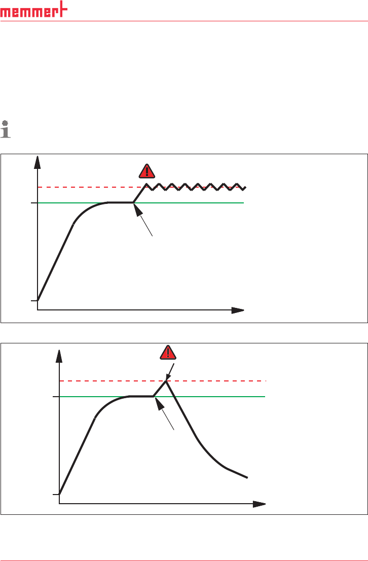
If the manually set monitoring temperature is exceeded, temperature monitoring takes over
temperature control and begins to regulate the monitoring temperature (TWW, Fig. 17) or
switches off the heating (TWB, Fig. 18).
The two types of temperature monitoring are only available for appliances equipped with
a second temperature sensor (option A6). For appliances with only one temperature
sensor, only TWW is available.
t
°C
Setting Max Alarm
Set temperature
Controller error
Emergency operation
Fig. 17 Schematic diagram of how the TWW temperature monitoring system works
t
°C
heating switched off by TWB
Setting Max Alarm
Set temperature
Controller error
Fig. 18 Schematic diagram of how the TWB temperature monitoring works (only if equipped
with a second temperature sensor, option A6)